Multi-purpose periscope with display and overlay capabilities

a multi-purpose, optical periscope technology, applied in the field of optical periscopes, can solve the problems of inability to use periscopes and other optical sights, inability to perform degraded mode training, and compromise performan

Inactive Publication Date: 2011-02-03
OASIS ADVANCED ENG
View PDF18 Cites 35 Cited by
  • Summary
  • Abstract
  • Description
  • Claims
  • Application Information

AI Technical Summary

Problems solved by technology

Two major shortcomings were the inability to use the periscopes and other optical sights in the training and the inability to perform degraded mode training.
This method of displaying imagery has the intrinsic problem of introducing displays into an already space constrained vehicle compartment.
However, the integration is by static combiner elements which inevitably involve compromises in performance.
Specifically, a large portion of the outside light is lost when the device is used to provide an optical view of the outside world and a large portion of the display light is wasted when the device is used to provide a display image.
Though this approach is an improvement over the static combiner method, it has inherent issues in that power must be continually applied when the image combiner capability is utilized and when power is removed, intentionally or through power failure, the combiner will cause the view to be degraded.
This implies that the device must be continuously powered in order for the crewmember to use the periscope in normal operation mode and that the loss of power will make the periscope unusable.
Unfortunately the angles of incidence required to produce TIR do not permit the large field of view generally required of ground vehicle periscopes.

Method used


Image

  • Multi-purpose periscope with display and overlay capabilities
  • Multi-purpose periscope with display and overlay capabilities
  • Multi-purpose periscope with display and overlay capabilities

Examples


embodiment

Preferred Embodiment

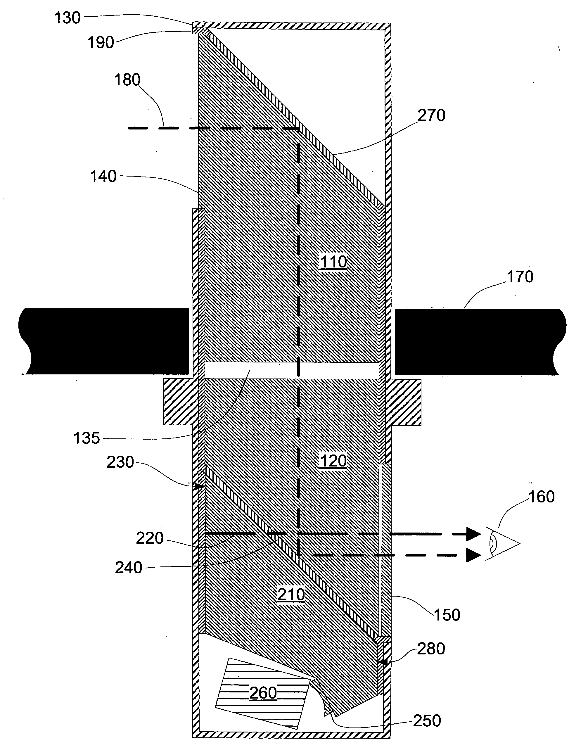
[0056]FIG. 7A, FIG. 7B, and FIG. 7C show identical cross-sections of the Cholesteric Liquid Crystal (CLC) Electronically Switchable Mirror (ESM) in different states. FIG. 7A represents the reflective state of the CLC ESM. Both layers of the ESM are in their naturally reflective state as there is no applied electrical potential V1 or V2. The incident outside light 730 enters the CLC ESM and hits Left-Handed Circularly Polarized (LHCP) CLC layer 320 where the LHCP portion 735 is reflected. The remaining portion of the light continues until it hits Right-Handed Circularly Polarized (RHCP) CLC layer 315 where the RHCP portion 740 of the light is reflected. A small portion of the incident light is not reflected by either CLC layer but this is not shown in the figure.

[0057]FIG. 7B represents the transparent state of the ESM. Both layers of the ESM are in their transparent state due to the application of electrical potentials V1 and V2. The electrical potential creates ...


PUM

PropertyMeasurementUnit
transparentaaaaaaaaaa
frequencyaaaaaaaaaa

Abstract

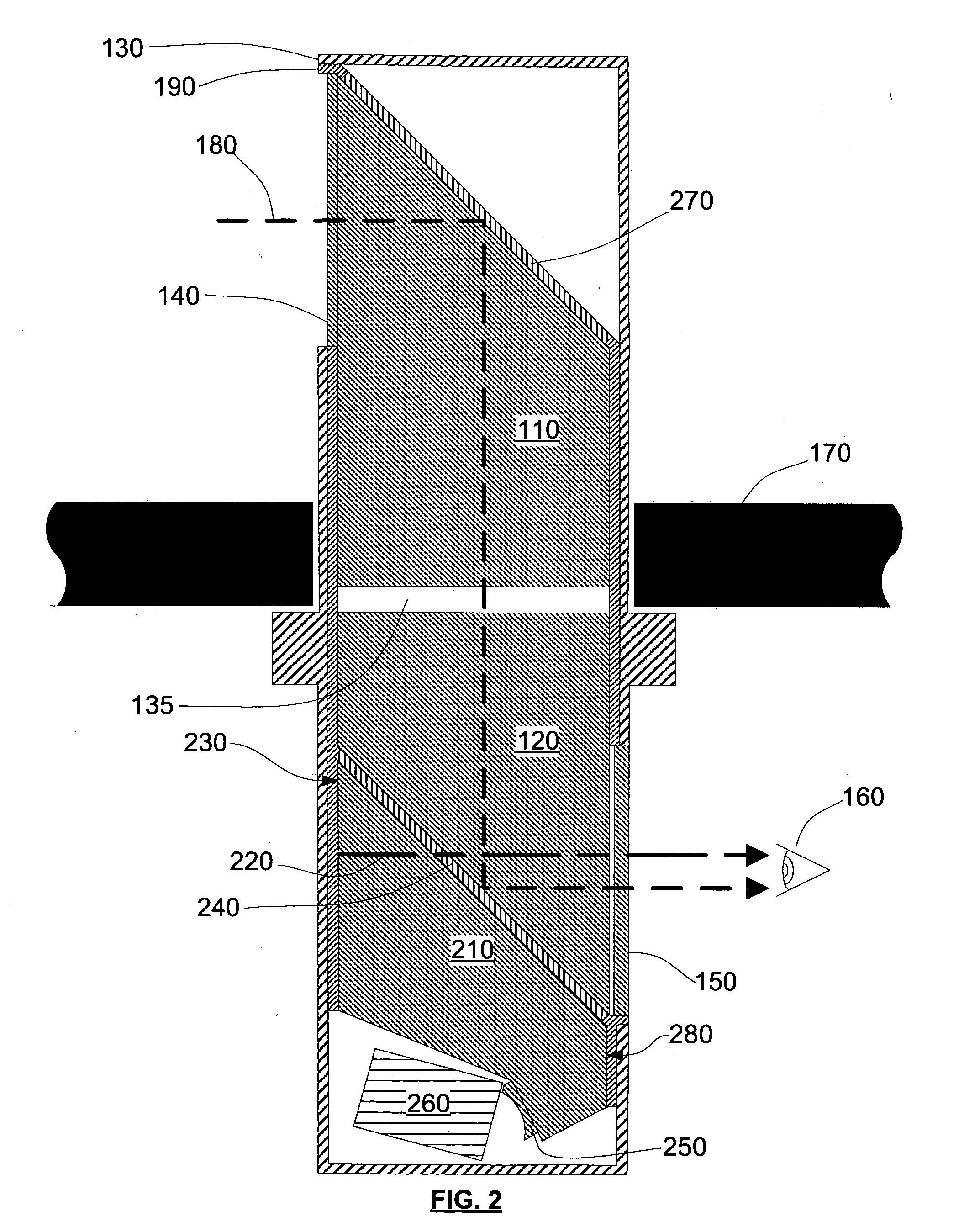
A collimated periscope that is switchable between a normal optical view of the outside, a display view, and an overlay view in which the outside view and display view are combined. The switching element is an electronically switchable mirror with primarily reflective, primarily transparent, and intermediate states, depending on the application of electrical potentials.

Description

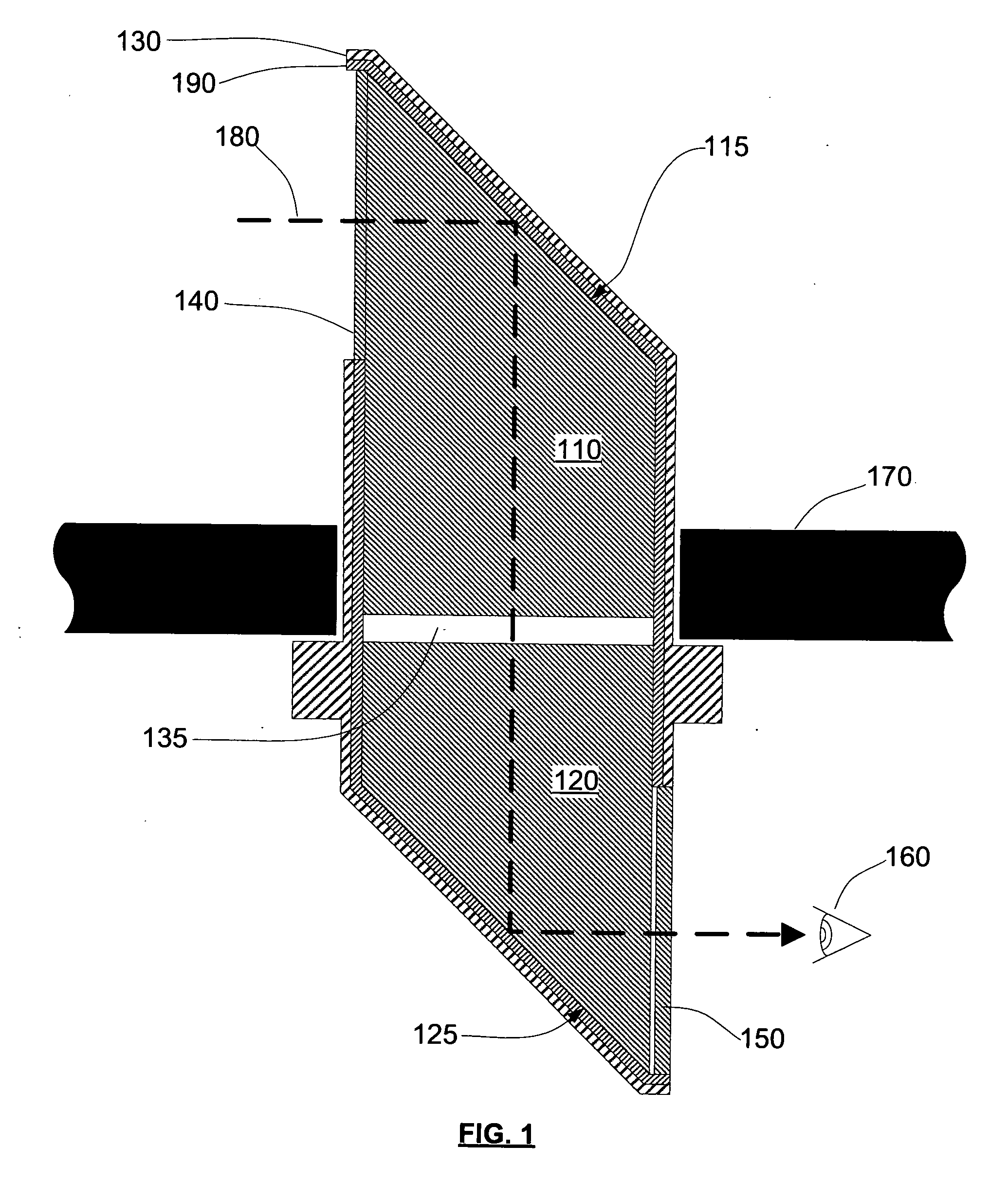
CROSS-REFERENCE TO RELATED APPLICATIONS[0001]This is a continuation in part application of Ser. No. 11 / 947,682, filed Nov. 29, 2007.FEDERALLY SPONSORED RESEARCH[0002]The US Government has Government Purpose Rights to portions of this invention.SEQUENCE LISTING OR PROGRAM[0003]Not ApplicableBACKGROUND OF THE INVENTION[0004]1. Field of Invention[0005]This invention relates to optical periscopes with integrated video display capabilities.[0006]2. Prior Art[0007]Optical periscopes as described in U.S. Pat. No. 2,361,050 have been in use on ground combat vehicles such as tanks and infantry vehicles for many years. These periscopes are generally wide field of view devices composed mainly of solid glass or acrylic prisms with mirrored surfaces. A cross-section of a conventional periscope is shown in FIG. 1. The armor of the vehicle is represented by 170. Periscopes can be designed to be inserted from outside or inside the vehicle. The variety shown is inserted from the inside. The periscop...

Claims


Application Information

Patent Timeline
Patent Type & Authority Applications(United States)
IPC IPC(8): G02F1/19G02B27/30G02B27/14G02B27/28
CPCF41G1/40G02B5/30G02B23/08G02B23/105G02B27/01F41H5/266G02B2027/011G02B2027/0112G02B2027/012G02B2027/0138G02B27/0101
Inventor MINOR, JEFFREY WAYNEDAVIES, HENRY CLARENCESCHWARTZ, EDWARD CHARLESKLINGENSMITH, MICHAEL JAMESRYAN, THOMAS PATRICK
Owner OASIS ADVANCED ENG
Why Eureka
Try Eureka