
Electronic device and magnetic latching mechanism therefore

a technology of magnetic latching and electronic device, which is applied in the direction of portable computer details, electric apparatus casings/cabinets/drawers, instruments, etc., can solve the problems of unable to lock the display closed, easy to break, and designers of laptop computers, etc., and achieve the effect of ensuring the display is open

Inactive Publication Date: 2011-02-03
LIGTENBERG CHRIS +1
View PDF83 Cites 88 Cited by
  • Summary
  • Abstract
  • Description
  • Claims
  • Application Information

AI Technical Summary

Problems solved by technology

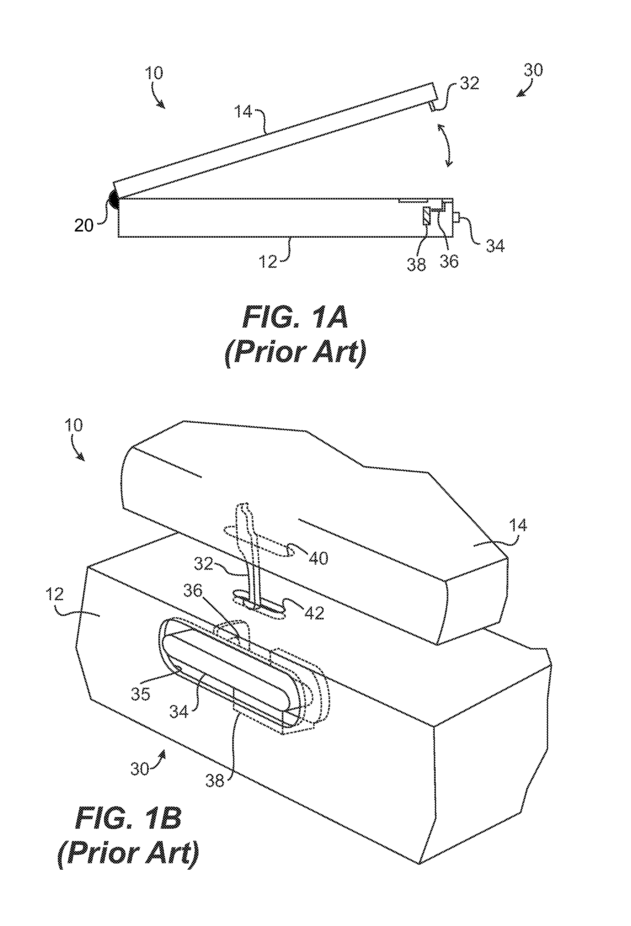
Unfortunately, several structural issues with prior art hook and catch interlocks and counterbalance clutches pose problems for designers of laptop computers.
Although these prior art mechanisms are effective, they are susceptible to breakage.
For example, a hook, catch, or spring of a latch mechanism can break simply through use, rendering the display incapable of being locked closed.
If a hinge between a display and a body has been slightly damaged, portions of a latch mechanism may be misaligned and not work properly.
In addition, portions of the latch mechanism such as the hook may be exposed on the display or the body after opening and can be broken inadvertently.
Likewise, structural issues with prior art counterbalance clutches pose problems for laptop designers.
Thus, the clutches have built in stresses that can cause failure over time.
These clutches can also be damaged if the display is inadvertently moved relative to the body in unwanted directions.
For example, when the display is closed and the clutches are loaded, any injury to the hinge area by dropping the laptop can damage the clutch and / or hinges.

Method used


Image

  • Electronic device and magnetic latching mechanism therefore
  • Electronic device and magnetic latching mechanism therefore
  • Electronic device and magnetic latching mechanism therefore

Examples


Embodiment Construction

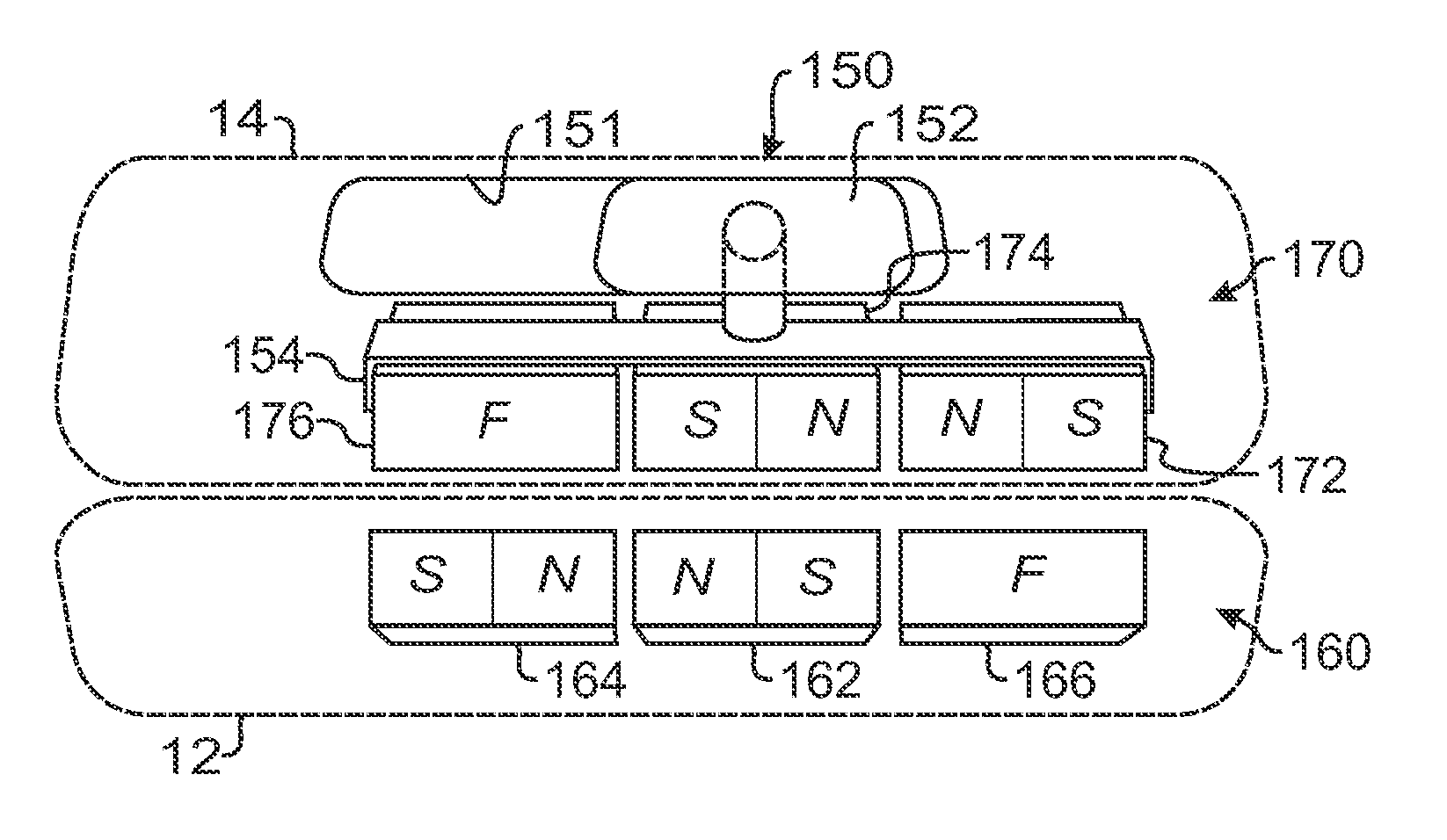
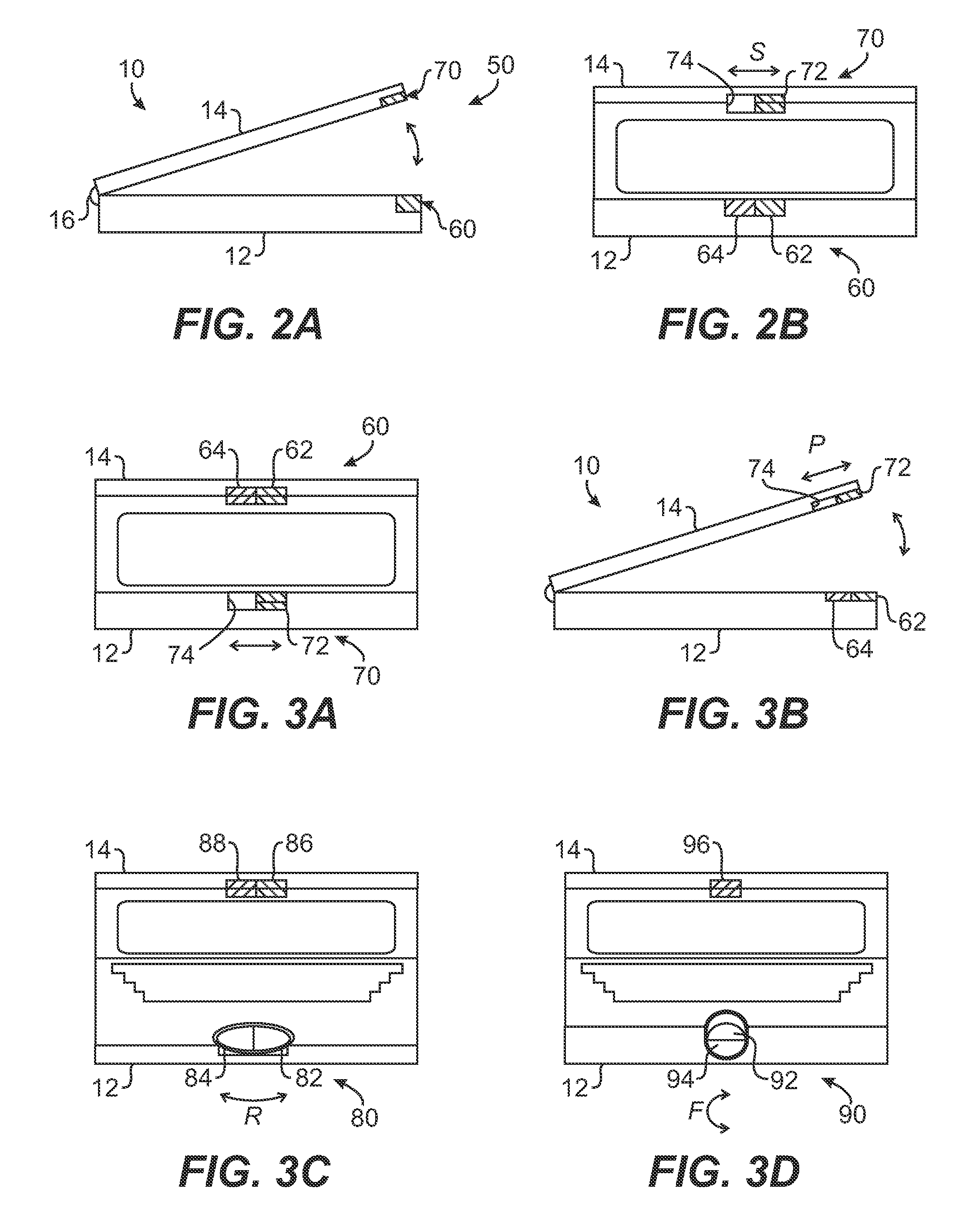
[0025]Referring to FIGS. 2A-2B, an electronic device 10 is illustrated in a side view and a front view. In the present example, the electronic device 10 is a laptop computer having a body 12 for internal electronics (not shown) and having a visual display 14 hingedly connected to the body 12 by a hinge 16. It will be appreciated, however, that the teachings of the present disclosure are applicable to other electronic devices, such as portable CD or DVD players, PDAs, calculators, and cell phones, for example, which have first and second body portions hingedly connected together and which can further have a display on the first body hingedly connected to the second body having internal electronics.

[0026]The electronic device 10 has a latch and pop-up mechanism 50 according to certain teachings of the present disclosure. In the present embodiment, the disclosed mechanism 50 achieves latching of the display 14 to the body 12 and achieves pop-up of the display 14 from the body 12. Altho...


PUM

PropertyMeasurementUnit
contrastaaaaaaaaaa
weightaaaaaaaaaa
thresholdaaaaaaaaaa

Abstract

A magnetic latch for a display of a laptop computer is disclosed. The latch uses magnetic attraction to maintain the display closed and uses magnetic repelling forces to pop-up the display when opened. The latch includes one or more magnetic elements in the body of the laptop and at least one magnetic element in the display. When the display is closed, the magnet element in the display is positioned adjacent the magnet element in the body having an opposite polarity so that the magnet elements are attracted to one another. To pop-up the display, the user moves the magnetic element in the display so that it meets the magnetic pole in the body having the same polarity. When these meet, the repelling force between them causes the display to open slightly so that a user can then readily open the display.

Description

CROSS-REFERENCE TO RELATED APPLICATIONS[0001]This application is a continuation of U.S. application Ser. No. 11 / 302,907, filed 13 Dec. 2005, which is incorporated herein by reference, to which priority is claimed, and which was filed concurrently with U.S. patent application Ser. No. 11 / 302,801, which is incorporated herein by reference in its entirety.FIELD OF THE DISCLOSURE[0002]The subject matter of the present disclosure generally relates to a latch for a laptop computer and more particularly relates to a magnetic latch for a laptop computer that uses magnetic attraction to keep the display closed and uses magnetic repulsion to pop-up the display for opening.BACKGROUND OF THE DISCLOSURE[0003]Laptop or network computers have a body housing internal components and have a display attached to the body. The display is typically hinged to the body so that the display can be opened and closed relative to the body. In the past, mechanical latches have been used on laptop displays to mai...

Claims


Application Information

Patent Timeline
Patent Type & Authority Applications(United States)
IPC IPC(8): H05K5/00H01F7/02
CPCE05C19/16G06F1/1616G06F1/1679Y10T24/32H05K5/0221Y10S292/37G06F1/1613Y10T292/11Y10T292/0999
Inventor LIGTENBERG, CHRISDEGNER, BRETT
Owner LIGTENBERG CHRIS
Learn More