
Marker processing method, marker processing device, marker, object having a marker, and marker processing program

Inactive Publication Date: 2011-02-03
SEIKO EPSON CORP
View PDF7 Cites 12 Cited by
  • Summary
  • Abstract
  • Description
  • Claims
  • Application Information

AI Technical Summary

Benefits of technology

[0010]An advantage of some aspects of the invention is to provide a marker processing method, a marker processing device, and a marker each independent of the posture (position, rotation, or tilt) of the marker, independent of the size of the marker, resistant to the noise in the image, and capable of reducing the amount of processing for detecting the marker using the monochrome image instead of the hue information.
[0025]According to the aspects of the invention, since it is arranged that the centroid (the center of figure can also be adopted) of each of the regions labeled from the shot image is obtained, and the marker is detected based on the degree of overlap of the centroids of the regions corresponding respectively to the labels, it becomes possible to provide a marker processing method, a marker processing device, a marker, an object having the marker, and a marker processing program each of which is independent of the posture and the size of the marker, highly resistant to the noise in the image, and allowing reduction of an amount of processing for marker detection by using a monochrome image instead of hue information.

Problems solved by technology

However, according to the method of detecting the symmetrical property of the shape using the technology described above, since the positioning symbol, in which a ratio of dark and bright periods is set as dark:bright:dark:bright:dark=1:1:3:1:1 as shown in FIG. 2, is detected by scanning, there arises a problem that the detectable range of the symbol, which is rotated or tilted, becomes narrower depending on the scanning interval.
Further, since a high symmetrical property is required for the marker itself in order to cope with the cases in which the scanning line for detecting the marker traverses the marker in various directions, which problematically causes restriction on creating a number of markers.
Further, since it is only required that the dark and bright periods have the ratio of 1:1:3:1:1, and there is basically no limitation on the absolute periods, there arises a problem that the marker detection side is required to cope with the period variation due to the size of the marker.
Further, since the black / white inversion period is used as the marker, determination of the period becomes difficult when noise is mixed into the input image.
Therefore, there arises a problem that some measure against the noise becomes necessary.
In other words, the technology of the Document 1 has a problem that the marker detection depends on the posture (position, rotation, or tilt) of the marker, depends on the size of the marker, and is further influenced significantly by the noise in the image.
Therefore, there arises a problem that it is required to reduce the resolution of the image or to reduce the frame rate when capturing the image in order for achieving the amount of processing equivalent to that in the monochrome image.
Further, since the hue information in the shot image is significantly influenced by illumination conditions and so on, and is further influenced significantly by the white balance and so on of the camera used for shooting, there arises a problem that some countermeasures against these factors become necessary.
Further, since the pigment or the color material in the material constituting the marker to be used varies across the ages, there arises a problem that some countermeasures against the aging become necessary.

Method used


Image

  • Marker processing method, marker processing device, marker, object having a marker, and marker processing program
  • Marker processing method, marker processing device, marker, object having a marker, and marker processing program
  • Marker processing method, marker processing device, marker, object having a marker, and marker processing program

Examples


first embodiment

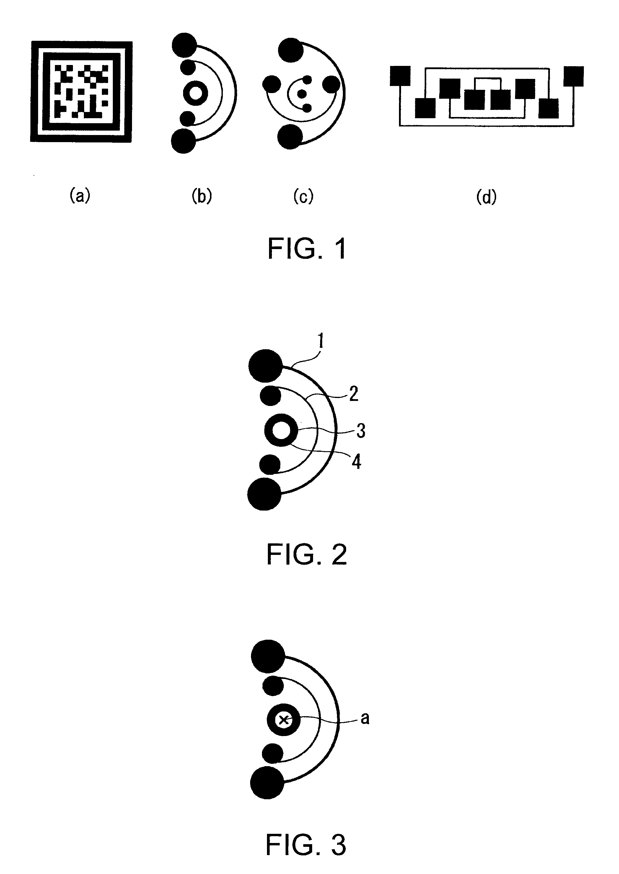
[0057]FIGS. 1A through 1D are diagrams showing some examples of a marker according to a first embodiment. In FIGS. 1A through 1D, each of the markers shown in FIGS. 1A through 1D is formed so that the centroid positions of the respective labels in each of the markers are identical to each other. Further, the markers shown in FIGS. 1A through 1D are each provided with four centroids.

[0058]FIG. 2 is a diagram for explaining constituents of the marker shown in FIG. 1B according to the first embodiment. The marker shown in FIG. 1B is constituted by a constituent 1, a constituent 2, a constituent 3 (black circle), and a constituent 4 (white circle) as constituents separated in accordance with white and black colors. These constituents are labeled in a labeling process described later for each region corresponding to the constituent.

[0059]FIG. 3 is a diagram for explaining centroids of the constituents of the marker shown in FIG. 1B according to the first embodiment. The marker shown in F...

second embodiment

[0120]Then, a second embodiment will be explained with reference to FIGS. 19 through 21, 22A through 22L, and 23A through 23L. In the first embodiment, the marker determination is performed with respect to the regions labeled by the region labeling section 104 using the multiplicity as a degree of overlap of the centroids of the respective regions.

[0121]In the second embodiment, identification of a type of the marker is further performed with respect to the regions labeled by the region labeling section 104.

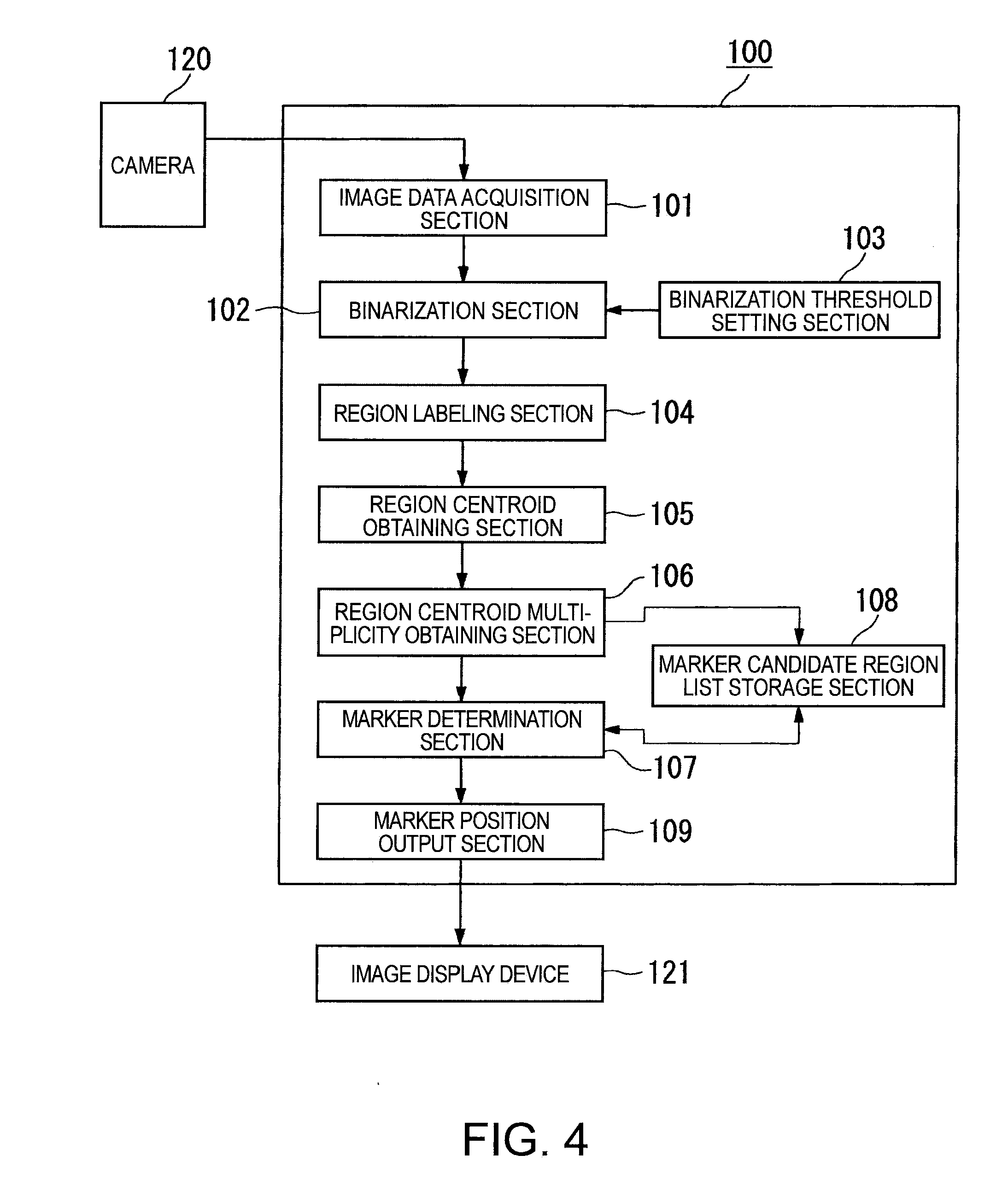
[0122]FIG. 19 is a block diagram showing an example of a configuration of the marker processing device according to the second embodiment. The marker processing device 100 is composed of an image data acquisition section 101, a binarization section 102, a binarization threshold setting section 103, a region labeling section 104, a region centroid calculation section 105, a region centroid multiplicity calculation section 106, a marker determination section 107, a marker candidate...

third embodiment

[0139]Then, a third embodiment will be explained with reference to FIGS. 24 through 27. The third embodiment relates to a method of forming the marker embedded with additional information. As explained with reference to FIGS. 17A through 17F of the first embodiment, since the only requirement of the marker, the marker processing method, and the marker processing device of the invention is that a predetermined number of centroids of the regions (labels) of the element overlap with each other, if a redundant element is embedded in a space other than the region, substantially the same advantage can be obtained.

[0140]An example of a method of embedding the redundant information into the marker will be explained with reference to FIGS. 24 through 27. FIG. 24 shows a flowchart of a process of embedding additional information into the marker. FIG. 25 is a diagram for explaining a method of forming a protective area-added marker. FIG. 26 is a diagram for explaining a method of adding data t...


PUM


Abstract

A marker processing method includes: (a) binarizing a shot image; (b) labeling one or more constituents of the image detected based on the image binarized in step (a); (c) obtaining a region centroid of each of the constituents corresponding to the respective labels processed in step (b); (d) obtaining a degree of overlap of the region centroids of the constituents corresponding respectively to the labels, obtained in step (c); and (e) detecting a marker based on the degree of overlap of the region centroids obtained in step (d).

Description

BACKGROUND[0001]1. Technical Field[0002]The present invention relates to a marker processing method, a marker processing device, a marker, an object having a marker, and a marker processing program.[0003]2. Related Art[0004]As a method of detecting a marker out of an image obtained by shooting an object attached with the marker there are known a method of detecting a symmetrical property of the shape and a method of detecting a combination of colors.[0005]As a method of detecting a symmetrical property of a shape, there is proposed a method of detecting a two-dimensional code having a positioning symbol. The positioning symbol is disposed at a predetermined position, and the location and the rotational angle of the two-dimensional code can be obtained using the positioning symbol detected in the image thus shot (see, e.g., JP-A-7-254037 (Document 1)).[0006]As a method of detecting a combination of colors, there is proposed a method of detecting a hue region entirely surrounded by a ...

Claims


Application Information

Patent Timeline
IPC IPC(8): G06K9/00G06V10/44
CPCG06K9/4604G06K7/1443G06K19/06037G06V10/44
Inventor INAZUMI, MITSUHIRO
Owner SEIKO EPSON CORP
Learn More