Reagent tube

a technology of reagent tubes and reagents, applied in the field of reagent tubes, can solve the problems of high cost and only operable by trained clinicians, many diagnostic analyses can only be done with highly specialist equipment, incur shipping costs and transportation delays,

Active Publication Date: 2011-02-03
HANDYLAB
View PDF99 Cites 88 Cited by
  • Summary
  • Abstract
  • Description
  • Claims
  • Application Information

AI Technical Summary

Problems solved by technology

At present, however, diagnostic analyses no matter how routine have become a bottleneck in patient care.
For example, many diagnostic analyses can only be done with highly specialist equipment that is both expensive and only operable by trained clinicians.
This means that most hospitals are required to send out samples for analyses to these locations, thereby incurring shipping costs and transportation delays, and possibly even sample loss or mishandling.
Preparing samples for PCR is currently a time-consuming and labor intensive step, though not one requiring specialist skills, and could usefully be automated.
Sample preparation is labor intensive in part because of the number of reagents required, and the need for multiple liquid transfer (e.g., pipetting) operations.
Even a loss of a very small fraction of a processing volume could result in loss of a significant number of copies of target polynucleotide and thereby result in a concomitant loss of amplification and detection sensitivity and—potentially—a false negative diagnosis.
A major source of loss of liquid samples and solutions is from incomplete pipetting, where a pipette attempts to suck an entire quantity of fluid from a container, but where some fraction of that quantity is retained in the container, such as on the interior surfaces.
Such a shape of interior surface is likely to present an increased surface area on which solution may remain during pipetting, and are unlikely to effectively channel the solution towards the location of a pipette tip.
Although the '250 patent suggests that these grooves can be present in numbers of greater than two, and arranged radially with respect to the center of the vessel, such a configuration has at least the drawback that it would require a complex manufacture of the vessel, and are therefore limited to particular vessels, not necessarily those that are used in routine laboratory processes, such as biological sample preparation.

Method used


Image

  • Reagent tube
  • Reagent tube
  • Reagent tube

Examples


example 1

Reagent Tube

[0058]An exemplary reagent tube, showing various dimensions, is shown in FIGS. 4A-4D. Tolerances on the shown dimensions, during manufacture, are as follows: features≦0.5 inches are machined to within±0.010 inches; features<0.5 inches are machined to within±0.005 inches; feature locations, such as theoretical center points and theoretical center lines, are within±0.010 inches of those shown in the drawings. It is to be understood that dimensions can also be represented in their metric system equivalents without departing from the scope of the technology herein.

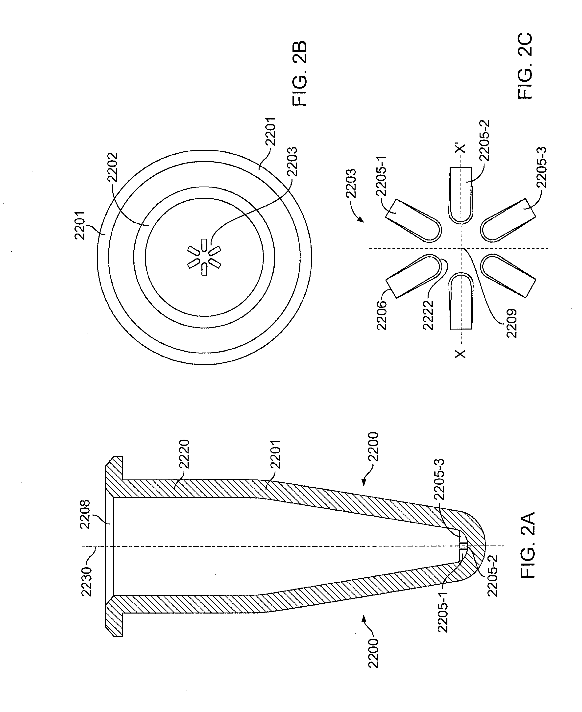
[0059]The cross-hatch area shown on the upper portion of the tube in FIG. 4C is an area on which a marking may be made, such as during manufacture, for the purpose of indicating product origin, identifying the batch, or for quality control.

[0060]The pattern of ridges shown in FIG. 4D is such that each ridge comprise a rectangular portion capped by a semi-circular arc, the semi-circular arc being disposed close to t...

example 2

Foil Piercing and Dissolution of Lyophilized Reagents

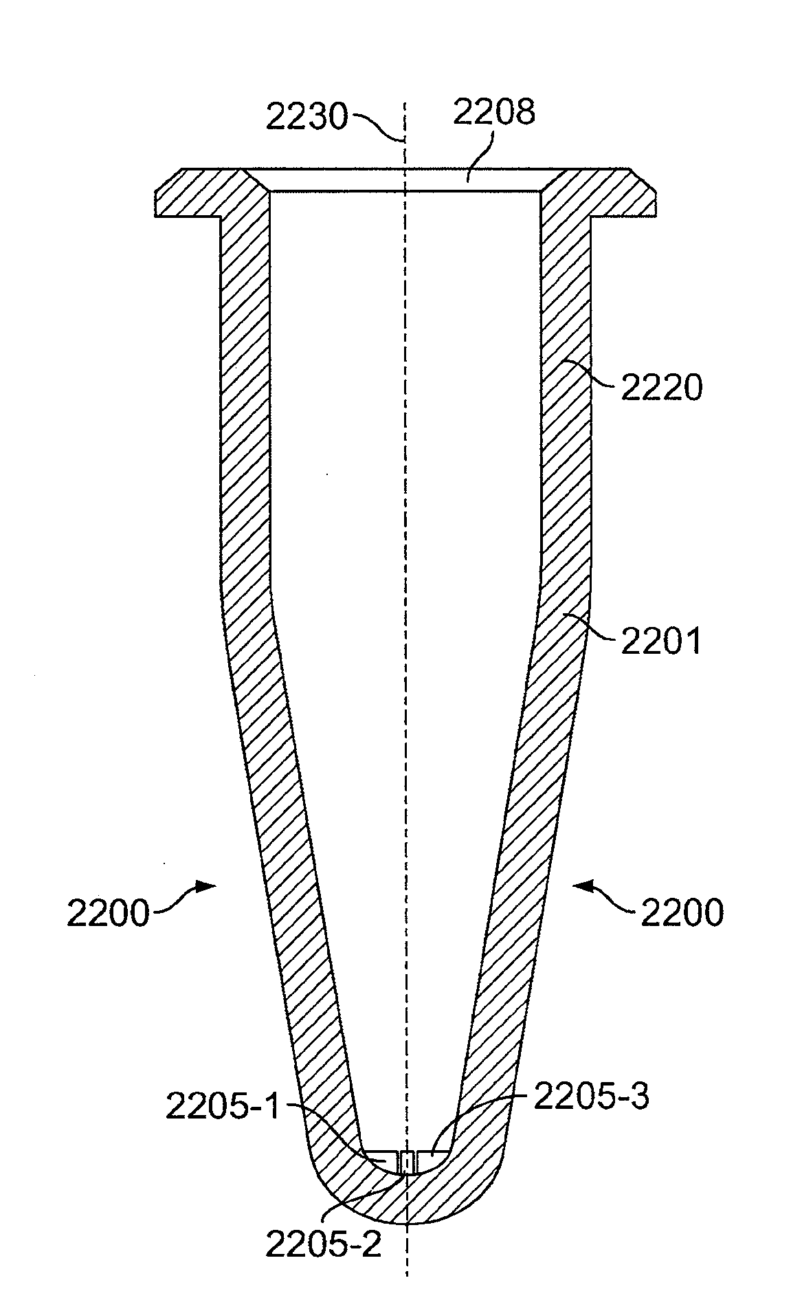
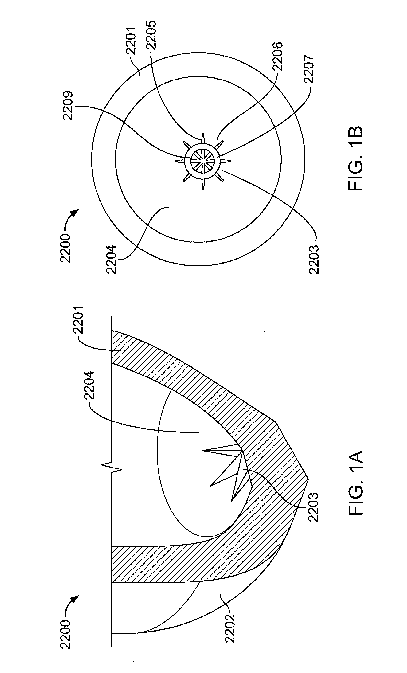
[0064]The containers of lyophilized reagents provided in conjunction with a holder as described herein are typically sealed by a non-plasticized aluminum foil. Aluminum foil bursts into an irregular polygonal pattern when pierced through a pipette and leaves an air vent even though the pipette is moved to the bottom of the tube. In order to save on reagents, it is desirable to dissolve the reagents and maximize the amount withdrawn from the tube. To accomplish this, a ridged-star (stellated) pattern is placed at the bottom of the container to maximize liquid volume withdrawn, and flow velocity in between the ridges.

[0065]Exemplary steps for dissolving solid particles, and withdrawing fluid are as follows:[0066]1. Pierce through the pipette and dispense the fluid away from the lyophilized material. If the pipette goes below the level of the lyophilized material, it will go into the pipette and may cause jamming of the liquid flow o...


PUM


Abstract

A reagent tube configured with a stellated shaped pattern, on its bottom interior surface, configured to facilitate complete or near-complete withdrawal of fluid from the tube, via a pipette tip. The reagent tube may be used for transporting reagents and for carrying out processing operations on biological samples with the reagents, such as preparing polynucleotides extracted from the sample for amplification.

Description

CROSS-REFERENCE TO RELATED APPLICATIONS[0001]This application is a continuation of U.S. patent application Ser. No. 12 / 178,557, filed on Jul. 23, 2008 which is a continuation-in-part of each of U.S. patent application Ser. No. 12 / 218,498, filed on Jul. 14, 2008, U.S. patent application Ser. No. 12 / 218,416, filed on Jul. 14, 2008, and U.S. patent application Ser. No. 12 / 173,023, filed Jul. 14, 2008, each of which claims the benefit of priority to U.S. provisional Patent Application Ser. No. 60 / 959,437, filed Jul. 13, 2007. All of the above patent applications are incorporated herein by reference in their entireties.BACKGROUND OF THE INVENTION[0002]1. Field of the Invention[0003]The technology described herein generally relates to reagent tubes designed to facilitate pipetting of small volumes of liquid from within, and more particularly to reagent tubes that are used in extracting microfluidic quantities of polynucleotides in solution following extraction from biological samples.[000...

Claims


Application Information

Patent Timeline
Patent Type & Authority Applications(United States)
IPC IPC(8): B01L3/14
CPCB01L3/5082B01L2200/026B01L2200/16B01L2300/0851F16K99/0001G01N2035/00881F16K99/0032F16K99/0044F16K99/0061F16K2099/0084F16K99/003
Inventor HANDIQUE, KALYANSPRINGER, THEODORE
Owner HANDYLAB
Why Eureka
Try Eureka