
Low profile rear tip for inflatable penile prostheses

a penile prosthesis and low-profile technology, applied in the field of inflatable penile prosthesis, can solve the problems of patient discomfort during operation, inability to satisfactorily mitigate, and relatively inefficient and costly construction

Active Publication Date: 2011-02-03
COLOPLAST AS
View PDF3 Cites 0 Cited by
  • Summary
  • Abstract
  • Description
  • Claims
  • Application Information

AI Technical Summary

Benefits of technology

The low profile rear tip facilitates easier surgical implantation, reduces post-operative discomfort, and is more efficient and cost-effective compared to traditional designs.

Problems solved by technology

Thus, rear tips of known IPPs heretofore have, in some cases, presented several drawbacks to physicians who implant them in patients and also to the patients themselves.
These deficiencies attributable to a relatively high and rigid rear tip profile have included, for example, a need for substantial anatomical dissection or preparation during implantation surgery, a need for a surgical technique which accommodates implantation of such a device, and post-operative discomfort to the patient due to presence of such a device in the patient's body.
However, such constructions may be relatively inefficient and costly to produce, and may still not satisfactorily mitigate the problems of a relatively high and rigid rear tip profile.
These publications teach rear constructions utilizing “compound curves” and “keyholes” to provide a device that may be “easier to implant and reduce trauma [by providing] a smaller effective width [or profile] during implantation, after implantation, or both.” However, these constructions may also be relatively inefficient and costly to produce, and may not satisfactorily mitigate the aforementioned problems.
Thus, an unmet need has existed for a low profile rear tip for IPPs that may overcome deficiencies of known devices.

Method used


Image

  • Low profile rear tip for inflatable penile prostheses
  • Low profile rear tip for inflatable penile prostheses

Examples


Embodiment Construction

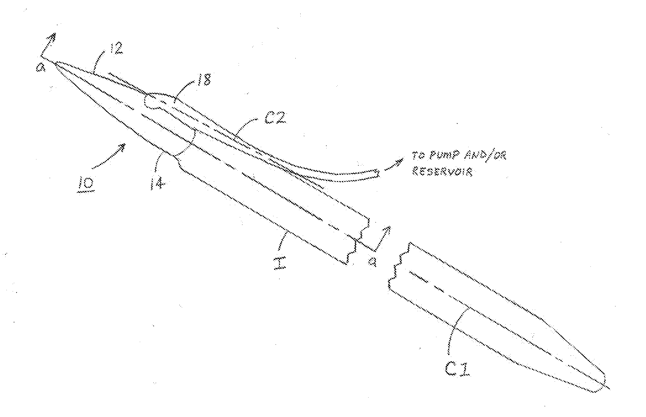
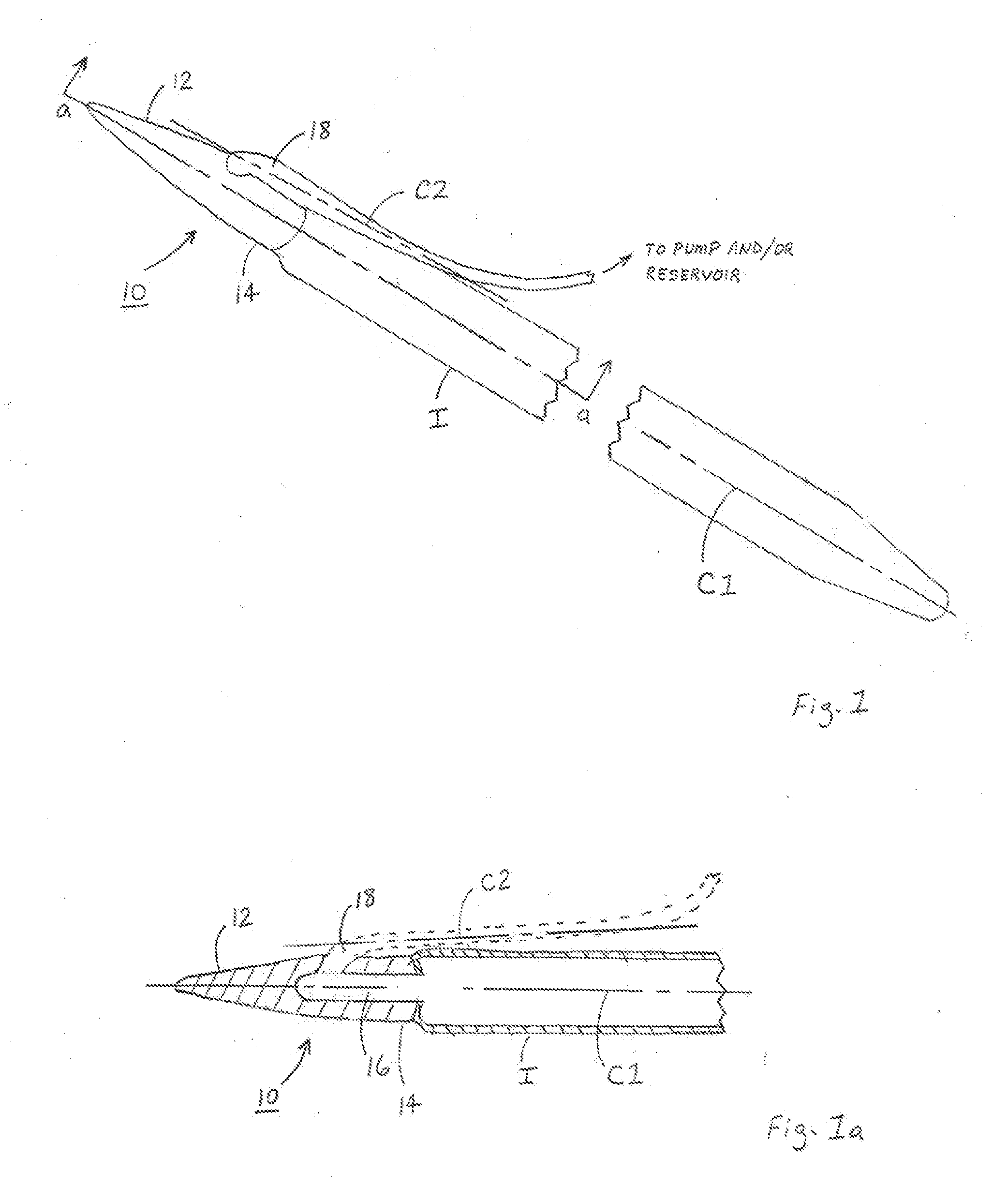
[0012]Illustrated in FIGS. 1 and 1a is an example of a low profile rear tip 10 (hereinafter, “rear tip 10”) for inflatable penile prostheses of the present invention, depicted as being connected to an IPP cylinder I. In this example, rear tip 10 could include a proximal end portion 12, a distal end portion 14 capable of being coupled to cylinder I along a major longitudinal axis C1 between proximal end portion 12, distal end portion 14, and cylinder I. Rear tip 10 could also include a fluid chamber 16 in distal end portion 14, with chamber 16 being in fluid communication with cylinder I. Rear tip 10 could further include a fluid conduit 18 having a strain relief portion and a tubing junction, integrally formed with distal end portion 14. Fluid conduit 18 could have a minor longitudinal axis C2, and be in fluid communication with fluid chamber 16 in distal end portion 14. Rear tip 10 could be constructed so that an elevation or angle between minor longitudinal axis C2 and major longi...


PUM


Abstract

A penile prosthetic system includes a pump connected between a reservoir and an inflatable penile implant. The inflatable penile implant includes a cylinder and a distal end portion connected to a distal end of the cylinder along a major longitudinal axis of the cylinder. The distal end portion forms a fluid chamber that is in fluid communication with the cylinder, and a fluid conduit is integrally formed to communicate with the fluid chamber in the distal end portion. The fluid conduit has a minor longitudinal axis that forms an angle with the major longitudinal axis of 5 degrees or less.

Description

FIELD OF THE INVENTION[0001]The present invention relates generally to inflatable penile prostheses. The invention relates specifically to a low profile rear tip for inflatable penile prostheses.BACKGROUND OF THE INVENTION[0002]Inflatable penile prostheses (or, as may be termed hereinafter, “IPPs”) are well known and have been in wide use. These devices are surgically implanted in male patients who, typically, are unable to achieve or sustain a penile erection due to a physical disability.[0003]IPPs typically comprise several components such as a fluid reservoir, a pump, a valve, at least one inflatable cylinder including a rear tip with a strain relief portion and a tubing junction, and various lengths of tubing which fluidly connect the fluid reservoir, the pump, the valve, and the strain relief portion of the inflatable cylinder or cylinders (hereinafter, whether singular or plural, “cylinder”). Typically the fluid reservoir is surgically implanted in the patient's abdomen, with ...

Claims


Application Information

Patent Timeline
Patent Type & Authority Applications(United States)
IPC IPC(8): A61F5/00
CPCA61F2250/0003A61F2/26
Inventor MORNINGSTAR, RANDY L.
Owner COLOPLAST AS
Learn More