Foot abduction apparatus

a technology for abduction apparatus and feet, applied in medical science, non-surgical orthopedic devices, etc., can solve the problems of limited horizontal and vertical movement of devices, difficult movement for users, etc., and achieve the effect of reducing the potential for allergic reactions and great comfor

Active Publication Date: 2011-02-03
MD ORTHOPAEDICS INC
View PDF13 Cites 4 Cited by
  • Summary
  • Abstract
  • Description
  • Claims
  • Application Information

AI Technical Summary

Benefits of technology

A third embodiment of the invention is similar to the first two and contains at least a second pivot point and an additional metal or plastic bar. The two bars are substantially in parallel and contain a means for attachment at each end. A connecting device is attached to each side of the bars. The bars may pivot about the coupling device in a horizontal direction while maintaining the bars in parallel. Each coupling device contains a third pivot point which may be attached to either a left footplate or a right footplate. The third pivot point allows movement in the vertical plane. Again the footplate contains a means to adjust and maintain the angle of outward rotation. A left shoe may then be attached to the left footplate and a right shoe attached to the right footplate. The user of this emb

Problems solved by technology

However, the devices allow the user limited movement in the horizontal and vertical planes.
Addi

Method used


Image

  • Foot abduction apparatus
  • Foot abduction apparatus
  • Foot abduction apparatus

Examples


second embodiment

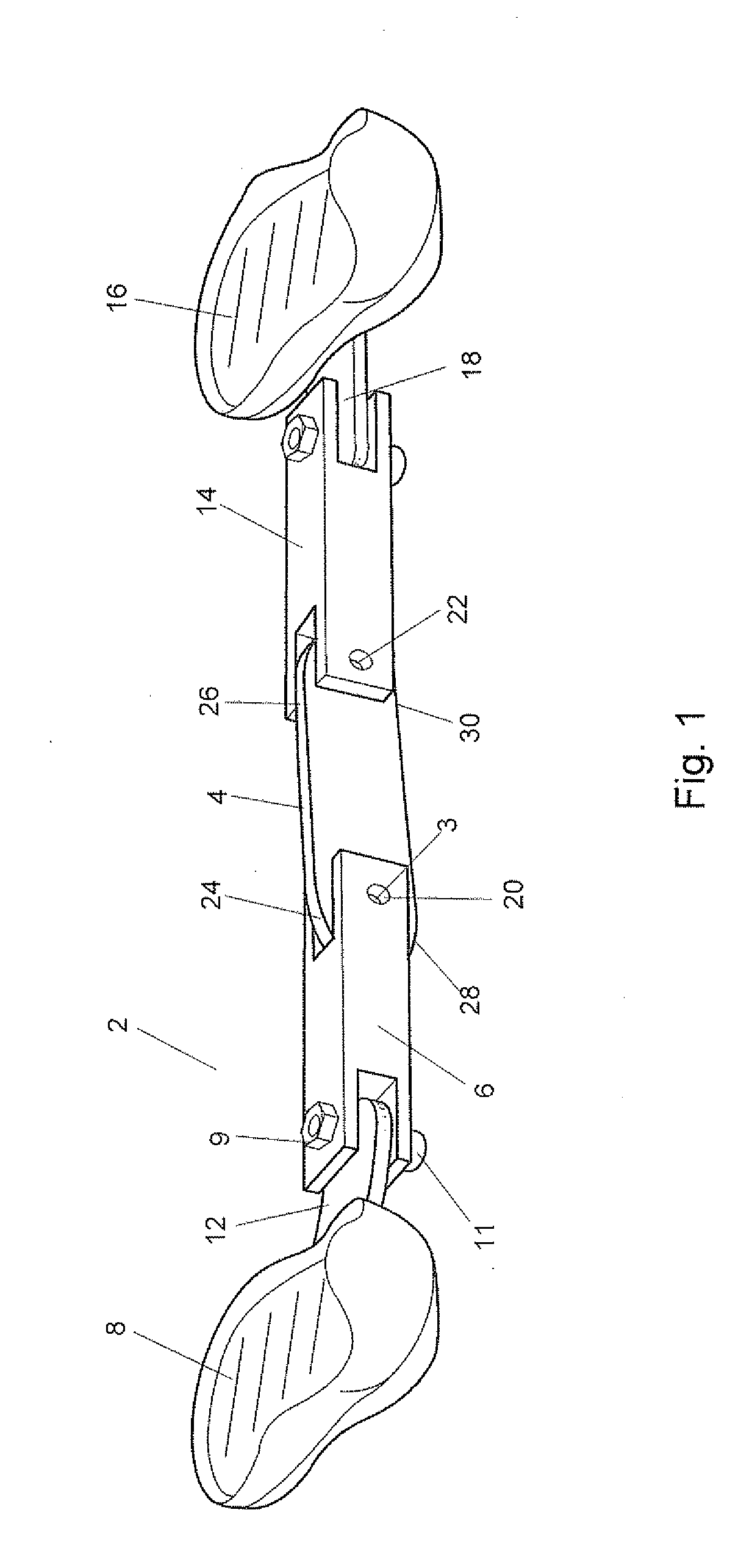
Now referring to FIG. 3 and FIG. 4, a foot abduction system 202 is detailed. The system 202 comprises a first rigid member 204, a second rigid member 206, a first coupling device 208, a second coupling device 210, a left plate 212, a right plate 214, a left shoe receiving member 216, and a right shoe receiving member 218. The first rigid member 204 and the second rigid member 206 lie within the same horizontal plane and are spaced such that they are substantially parallel with one another. Each rigid member 204, 206 are preferably made of metal or a rigid plastic and further comprise a first end 220, 222 respectively and a second end 224, 226 respectively. The first ends 220, 222 are selectively attachable to the first coupling device 208, while the second ends 224 and 226 are selectively attachable to the second coupling device 210.

The first coupling device 208 and the second coupling device 210 are preferably made of plastic and each further comprise three segments 230, 231, 232. ...

third embodiment

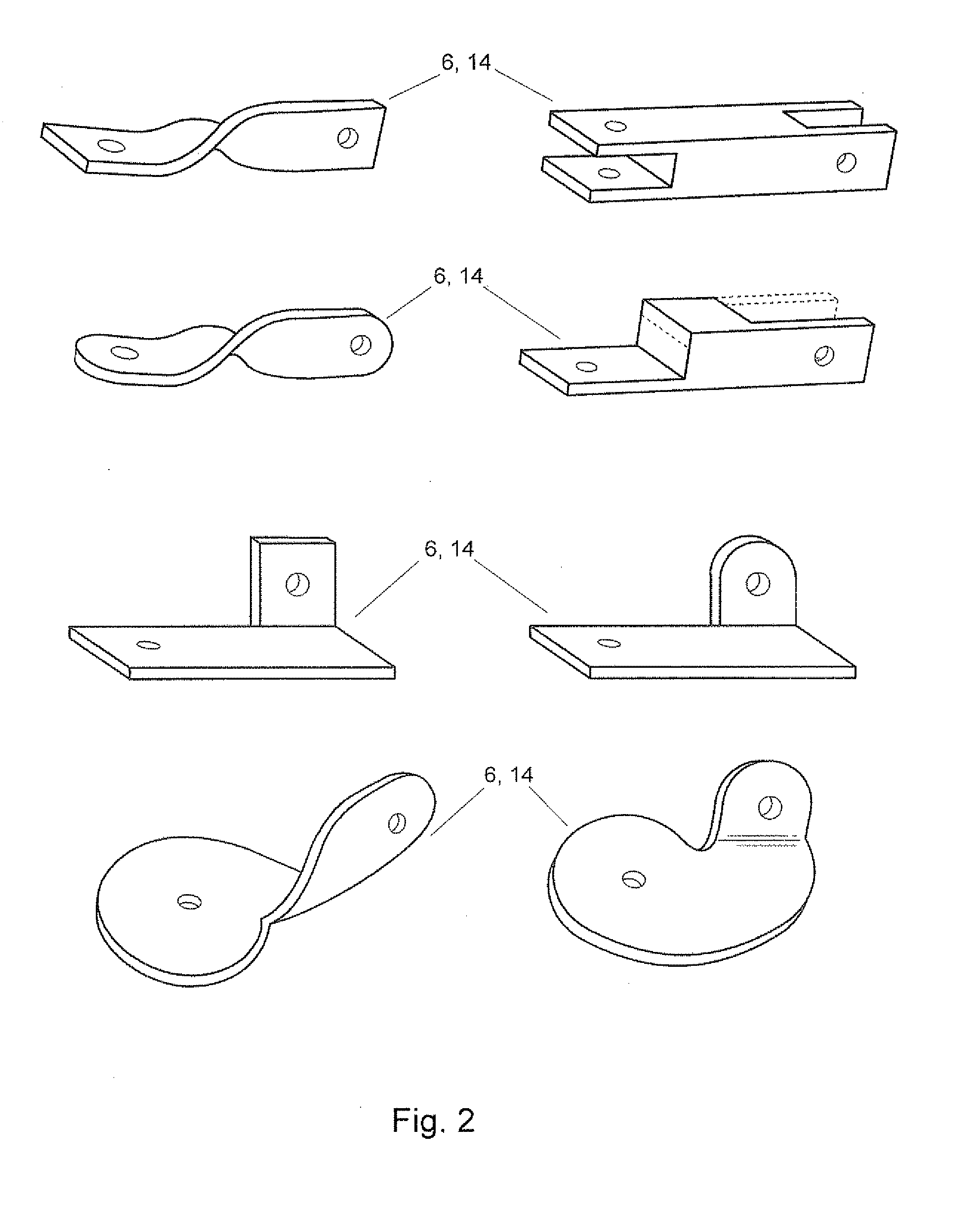
Now referring to FIG. 5 and FIG. 6, a foot abduction system 302 is detailed. The system 302 comprises a first rigid member 304, a second rigid member 306, a first coupling device 308, a second coupling device 310, a left plate 312, a right plate 314, a left shoe receiving member 316, and a right shoe receiving member 318. The first rigid member 304 and the second rigid member 306 lie within the same horizontal plane and are spaced such that they are substantially parallel with one another. Each rigid member 304, 306 are preferably made of metal or a rigid plastic and further comprise a first end 320, 322 respectively and a second end 324, 326 respectively. The first ends 320, 322 are selectively attachable to the first coupling device 308, while the second ends 324 and 326 are selectively attachable to the second coupling device 310.

The first coupling device 308 and the second coupling device 310 are preferably made of plastic or metal alloy and each further comprise three segments ...


PUM


Abstract

An improved foot abduction apparatus allowing movement in a horizontal and vertical plane. The embodiments allow a user to more easily manipulate the apparatus in one or both planes through the use of strategically placed pivot points. The device utilizes at least one rigid member attached to coupling devices which contain at least one pivot point. The specialized coupling devices may be selectively attached to shoe receiving member or plates which are well known in the art. Additionally the shoe receiving members are able to receive an improved shoe containing a sole member contained with a silicone boot.

Description

BACKGROUNDDr. Ignacio Ponseti is an internationally famous physician and surgeon specializing in the treatment and management of a childhood deformity commonly know as a club foot. Dr. Ponseti has for many decades promoted the use of a foot and ankle abduction device, or orthosis, that is used to correct and prevent relapses of the club foot deformity. These abduction devices typically consist of a rigid bar connected between shoes worn by the child which bar separates the feet of the child and holds the feet in an outward rotation or abduction. Typically, if the condition is diagnosed early enough, this device is worn full-time for a period of months, but during the period of treatment, the angle of outward rotation is periodically adjusted.The Ponseti technique, as it has become known throughout the world, has been highly successful in treating club feet without the necessity of corrective surgery. Many devices have been designed and used for many, many years in applying the Ponse...

Claims


Application Information

Patent Timeline
IPC IPC(8): A61F5/00
CPCA61F5/0127A61F5/0193
Inventor MITCHELL, JOHN
Owner MD ORTHOPAEDICS INC
Why Eureka
Try Eureka