Weapons control systems

a control system and weapon technology, applied in the direction of weapons, aiming means, sighting devices, etc., can solve the problems of individual control of auxiliary devices that can sometimes complicate the use of weapons, the cable and the like required to implement auxiliary devices can be cumbersome, and the operation of weapons can be affected, so as to address or ameliorate the risk of enemy fir

Inactive Publication Date: 2011-02-10
KLEIN AVNER
View PDF5 Cites 17 Cited by
  • Summary
  • Abstract
  • Description
  • Claims
  • Application Information

AI Technical Summary

Benefits of technology

[0043]a cable loom configuration coupling at least to the sight unit, the controller and the communications system such that disconnection of the cable loom c...

Problems solved by technology

One drawback of such auxiliary devices is that the individual controls of the auxiliary devices can sometimes complicate use of the weapon.
Additionally, the cables and the like required to implement the auxiliary devices can be cumbersome, ill-fitting and/or interfere with the operation of the weapon by, for example, snagging or catching on moving parts or the operator of the weapon.
Whilst the remote control device of WO 2005/022067 ameliorates some of the aforementioned drawbacks, it does not address or ameliorate the risk associated with enemy fire.
The remote control devi...

Method used


Image

  • Weapons control systems
  • Weapons control systems
  • Weapons control systems

Examples


Embodiment Construction

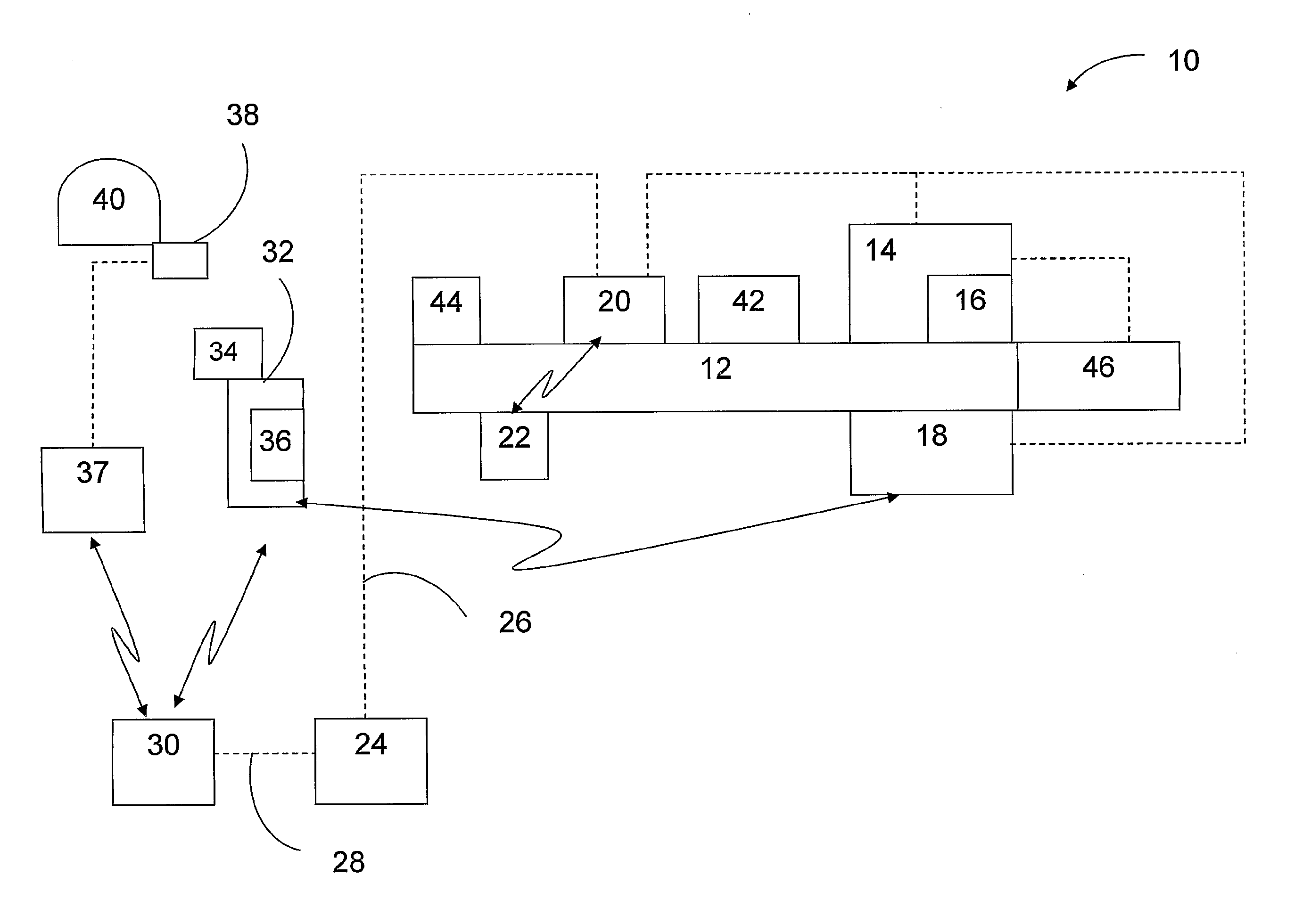
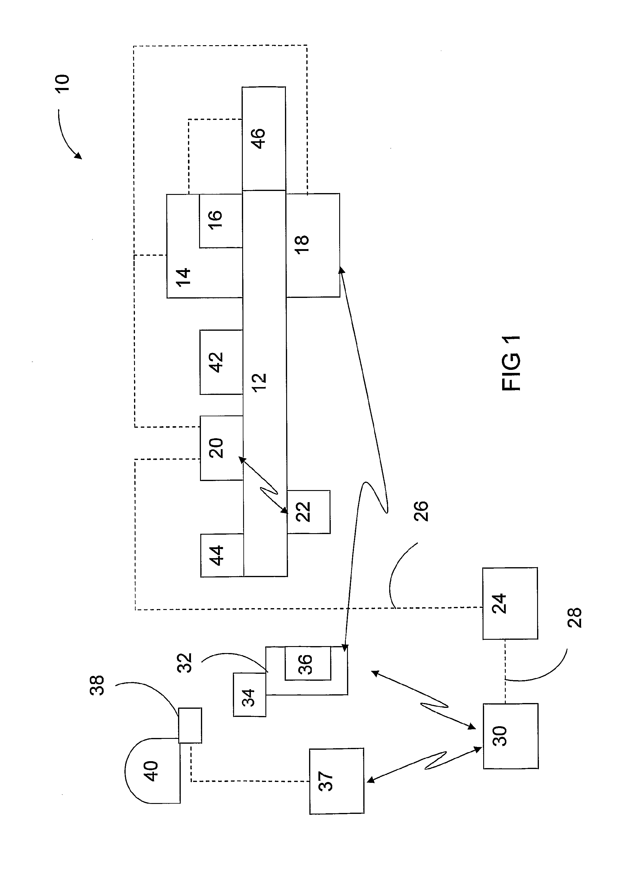
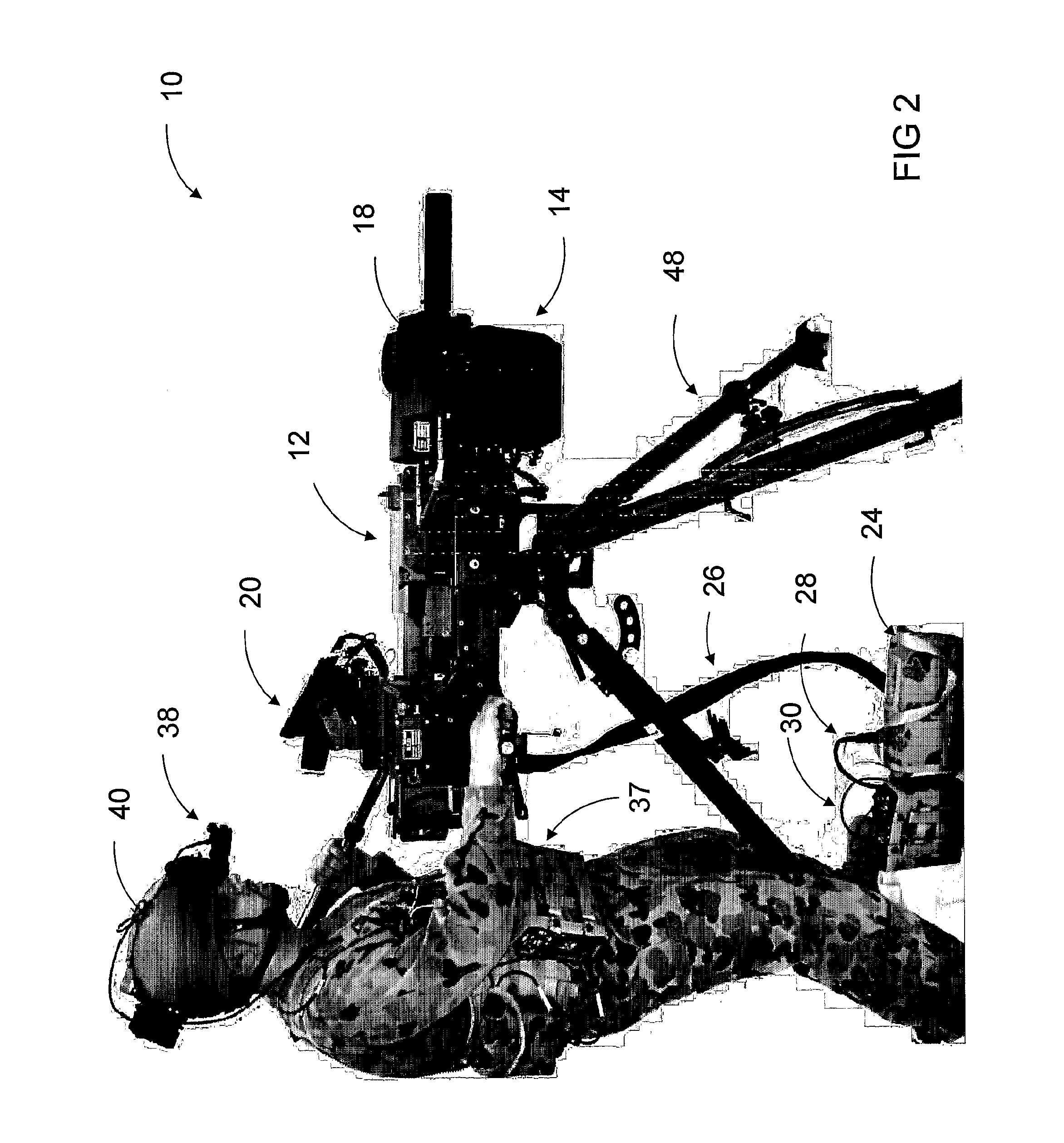
[0056]Referring to FIGS. 1 and 2, a control system 10 for a weapon 12 is provided according to embodiments of the present invention. The control system 10 comprises a sight unit 14 (also known as a Fire Control Unit (FCU) for mounting to the weapon 12 or to a cradle holding the weapon for capturing image data for targeting the weapon. According to different embodiments, the sight unit 14 comprises at least one camera 16 having a Charge Coupled Device (CCD) unit or an image intensified CCD unit. The CCD unit can have 752×582 pixels to support the PAL format or 768×494 pixels to support the NTSC format. The sight unit 14 can also comprise a laser rangefinder, motion sensors and other sensors, such as Molecular Electronic Transducers (MET) sensors (not shown).

[0057]According to some embodiments, the control system 10 comprises a thermal sight system (TSS) comprising one or more thermal cameras 18 for mounting to the weapon 12 or to a cradle holding the weapon or to another component of...


PUM


Abstract

Weapons control systems are disclosed including a handheld display and wiring loom configurations for weapons control systems. A control system for a weapon comprises a sight unit for mounting to the weapon for capturing image data for targeting the weapon. The control system also comprises a handheld display having a sight viewable by at least one eye of an operator of the weapon to view data associated with operation of the weapon including image data collected by the sight unit and a controller to control operation of the weapon. The control system also comprises a communication system coupled to be in communication with the handheld display and the sight unit to enable the operator to remotely view the data associated with operation of the weapon and simultaneously control operation of the weapon.

Description

FIELD OF THE INVENTION[0001]The present invention relates to weapons control systems. In particular, the present invention relates to control systems for portable weapons, such as, but not limited to, machine guns and automatic grenade launchers. However, the weapons control systems according to embodiments of the present invention are applicable to other types of weapons.BACKGROUND TO THE INVENTION[0002]Modern weaponry is typically equipped with one or more auxiliary devices, such as visible and / or infra-red aiming devices, thermal imaging systems, range finders, fire control systems, night vision image intensifiers, visible illumination devices, cameras and / or other sensors. Such auxiliary devices have specific applications, such as the image intensifier being for use in low light levels, and general applications, such as range finders, which are intended to be used in all conditions. However, all such auxiliary devices have the purpose of enhancing the performance of the weapon a...

Claims


Application Information

Patent Timeline
IPC IPC(8): F41G5/06
CPCF41G3/165F41G1/393
Inventor KLEIN, AVNER
Owner KLEIN AVNER
Why Eureka
Try Eureka