Eureka AIR delivers breakthrough ideas for toughest innovation challenges, trusted by R&D personnel around the world.

Concealed horizontal sidewall sprinkler

a sprinkler and sidewall technology, applied in fire rescue and other directions, can solve the problems of undesirable use, inconvenient installation, and inconvenient use, and achieve the effect of stable position

Inactive Publication Date: 2011-02-10
RELIABLE AUTOMATIC SPRINKLER
View PDF48 Cites 16 Cited by
  • Summary
  • Abstract
  • Description
  • Claims
  • Application Information

AI Technical Summary

Benefits of technology

[0015]Embodiments of the present invention may include one or more of the following features. The thermally-responsive element may include a pair of levers, each of which is connected to a plate of a soldered link. The rods may slide between a first position within the housing member, to a second, lower position extending from the housing member. In the second position, the rods may engage the housing members so as to assist in maintaining the deflector in a relatively stable position. Each of the rods may have at least one cylindrical portion and at least one frustoconical portion. Each of the housing members also may have at least one cylindrical portion and at least one frustoconical portion. The frustoconical portion of the rod may lodge in a frustoconical portion of the housing member.

Problems solved by technology

Some conventional horizontal sidewall sprinklers are installed in such a manner that their structure is visible, which is not aesthetically pleasing.
Moreover, the sprinkler's extending structure tends to invite improper use of the sprinkler, for example to hang clothing or other items.
Such improper use is undesirable, as it may render the sprinkler inoperable or cause unintended activation.
This arrangement tends to reduce air flow across the thermally-responsive element and correspondingly reduces the sensitivity of the sprinkler.
Moreover, such configurations often include deflector shelves that extend significantly beyond the vertical surface of the deflector and require covers that extend further from the wall.

Method used


Image

  • Concealed horizontal sidewall sprinkler
  • Concealed horizontal sidewall sprinkler
  • Concealed horizontal sidewall sprinkler

Examples


Embodiment Construction

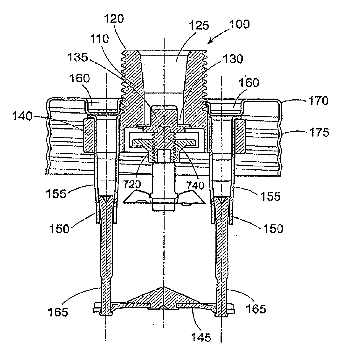
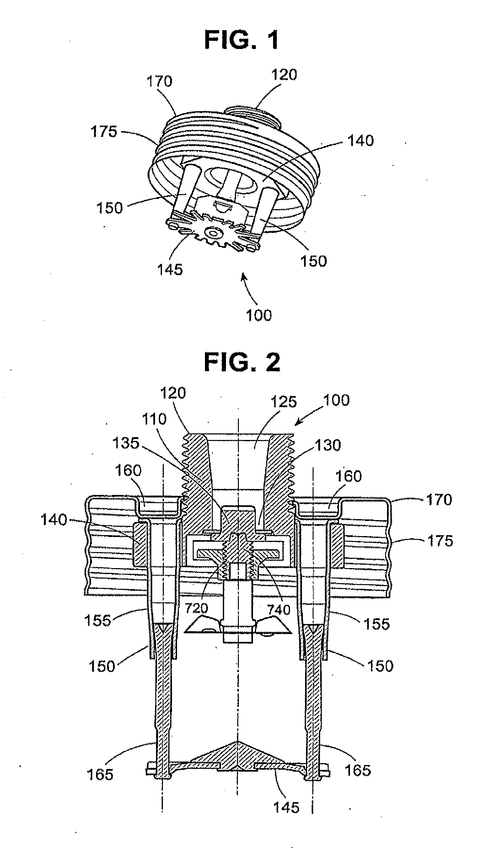
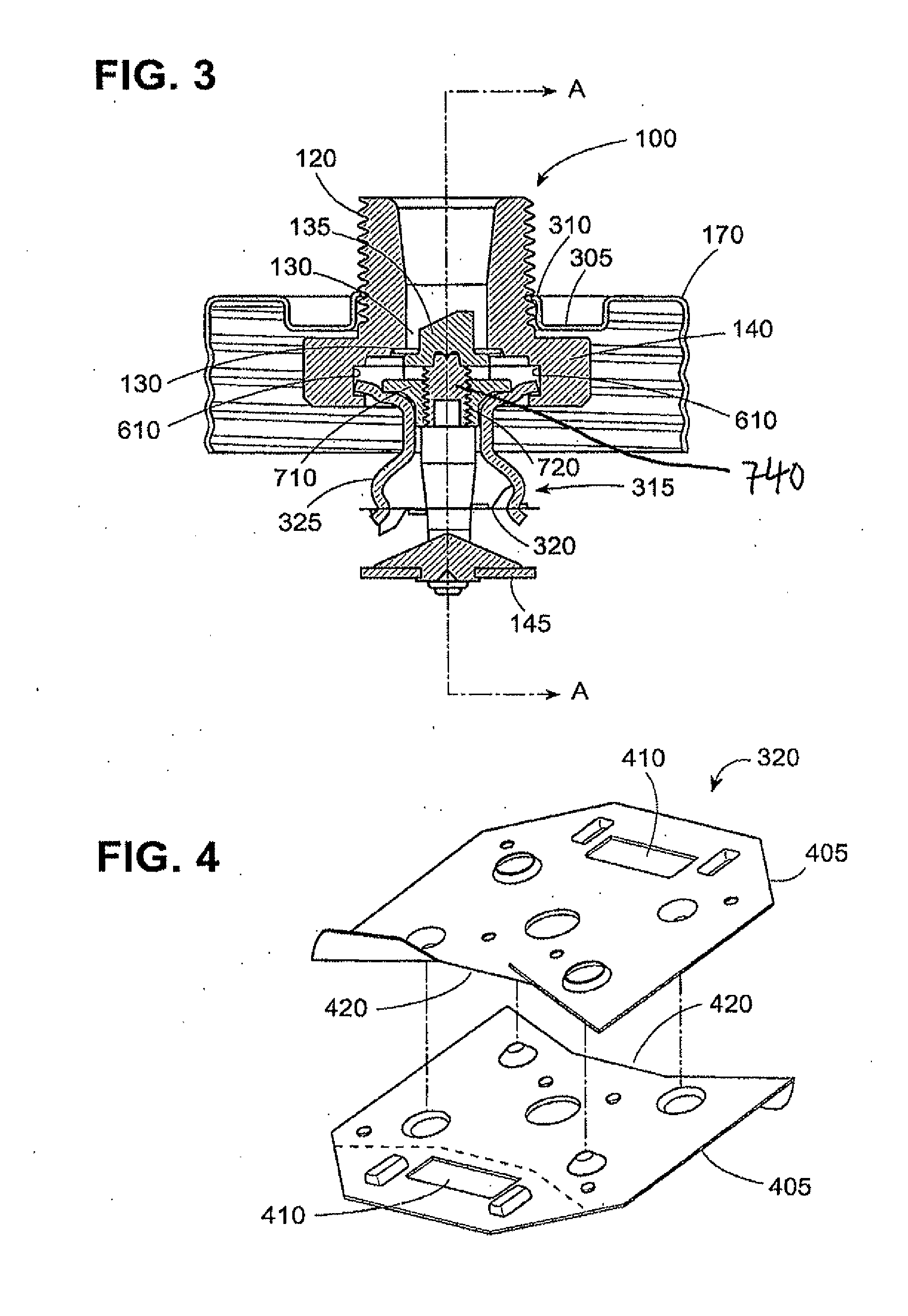
[0065]As shown in FIGS. 1 and 2, a pendent fire protection sprinkler 100 in accordance with the present invention has a body 110 with a threaded base 120 for connection to a conduit (not shown) for supplying pressurized fire-extinguishing fluid, such as water. The body 110 has an axial bore 125 with an outlet orifice 130 from which the fluid is output upon release of a seal cap 135. The output orifice 130 may have a diameter of, for example, ⅜ or 7 / 16 inch. The sprinkler may have a nominal K-factor of, for example, 4.3 or 5.6, respectively, which is defined by K=Q / √{square root over (p)}, where Q is the flow rate in gallons per minute and p is the residual pressure at the inlet of the sprinkler in pounds per square inch. The body 110 also has a hexagonal flange 140 around its output end. Of course in other embodiments, the flange 140 may have other shapes, including, for example, a rectangle and a diamond shape.

[0066]A deflector 145 is coupled to two deflector support members 150 on...


PUM


Abstract

A horizontal sidewall fire protection sprinkler has a deflector having a vertical face, transverse to the fluid flow from the output orifice, and a horizontal shelf positioned above and perpendicular to the vertical face. A portion of the horizontal shelf extends in the fluid flow direction by a first length, with respect to the vertical face, and this first length is less than about half of the total length of the horizontal shelf in the fluid flow direction. The sprinkler may be installed in a support cup having a raised mounting platform configured to receive the sprinkler body and a cylindrical outer surface. A horizontal or pendent fire protection sprinkler has a body having an output orifice and a flange and a seal cap to seal a flow of fluid from the output orifice and a thermally-responsive element positioned to releasably retain the seal cap. Housing members extend through and from the flange of the sprinkler body, and contain rods, each of which extends through the flange. A deflector is connected to ends of the rods.

Description

CROSS-REFERENCE TO RELATED APPLICATIONS[0001]This application is a continuation-in-part of U.S. patent application Ser. No. 10 / 974,397, filed Oct. 26, 2004, and is a continuation-in-part of U.S. patent application Ser. No. 11 / 848,103, filed Aug. 30, 2007, which is a continuation of U.S. patent application Ser. No. 10 / 974,106, filed Oct. 26, 2004 (now U.S. Pat. No. 7,275,603), the entire contents of each of which are incorporated herein by reference.BACKGROUND[0002]1. Field of the Invention[0003]The present invention relates to a pendent fire protection sprinkler with a drop-down deflector. The present invention further relates to concealed pendent sprinklers for residential applications. The present invention relates to horizontal sidewall fire protection sprinklers, including those having a deflector with a rearwardly positioned horizontal shelf, which reduces the overall length of the sprinkler to provide a low-profile configuration. Such sprinklers may also be mounted in a suppor...

Claims


Application Information

Patent Timeline
IPC IPC(8): A62C31/00
CPCA62C35/58A62C31/02A62C37/14
Inventor POLAN, GEORGE S.PAHILA, OLIVER S.MULTER, THOMAS L.
Owner RELIABLE AUTOMATIC SPRINKLER
Why Eureka
Eureka Blog
Learn More