Antenna with multiple coupled regions

Inactive Publication Date: 2011-02-10
HENG CHEW CHWEE +3
View PDF4 Cites 74 Cited by
  • Summary
  • Abstract
  • Description
  • Claims
  • Application Information

AI Technical Summary

Benefits of technology

[0010]In another embodiment, the grounded elements are parallel to the driven element. Alternatively, the grounded elements can be orthogonal with respect to the driven element. One or more elements can comprise an active tuning component. The active tuning component can be configured within or near a ground plane. Alternatively, one or more active components can be configured on an antenna element. One or more antenna elements can be bent. One or more antenna elements can be linear, or planar. One or more antenna elements can be fixedly disposed above a ground plane. Alternatively, one or more antenna elements can be configured within a ground plane.
[0011]In another embodiment, an antenna is provided having a high band radiating element and a low band radiating element. A switched network can be integrated with at least one of the high band or low band radiating elements.

Problems solved by technology

Other market driven constraints on antenna design include power efficiency, low loss, reduced size and low cost.

Method used


Image

  • Antenna with multiple coupled regions
  • Antenna with multiple coupled regions
  • Antenna with multiple coupled regions

Examples


Embodiment Construction

[0032]In the following description, for purposes of explanation and not limitation, details and descriptions are set forth in order to provide a thorough understanding of the present invention. However, it will be apparent to those skilled in the art that the present invention may be practiced in other embodiments that depart from these details and descriptions.

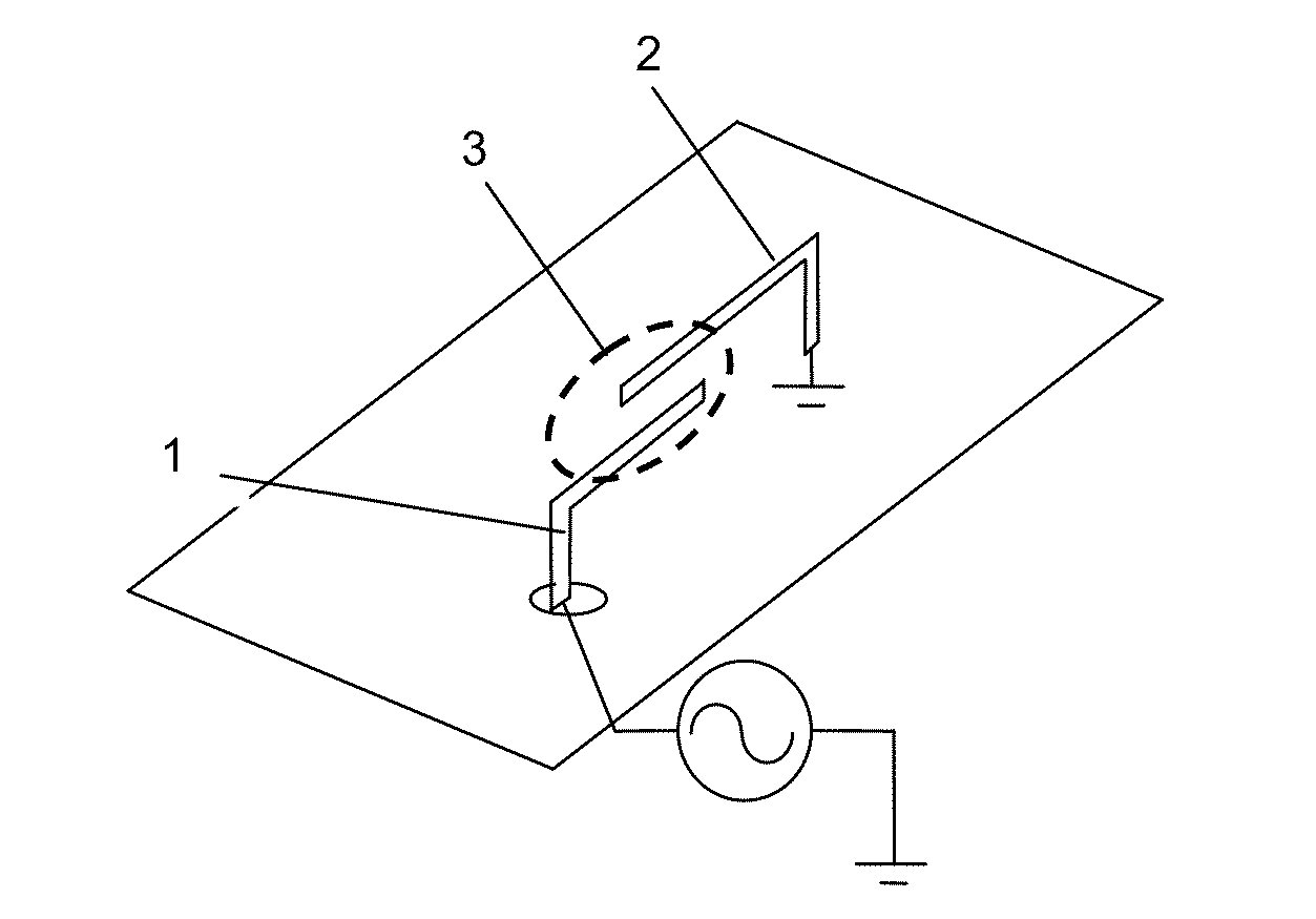
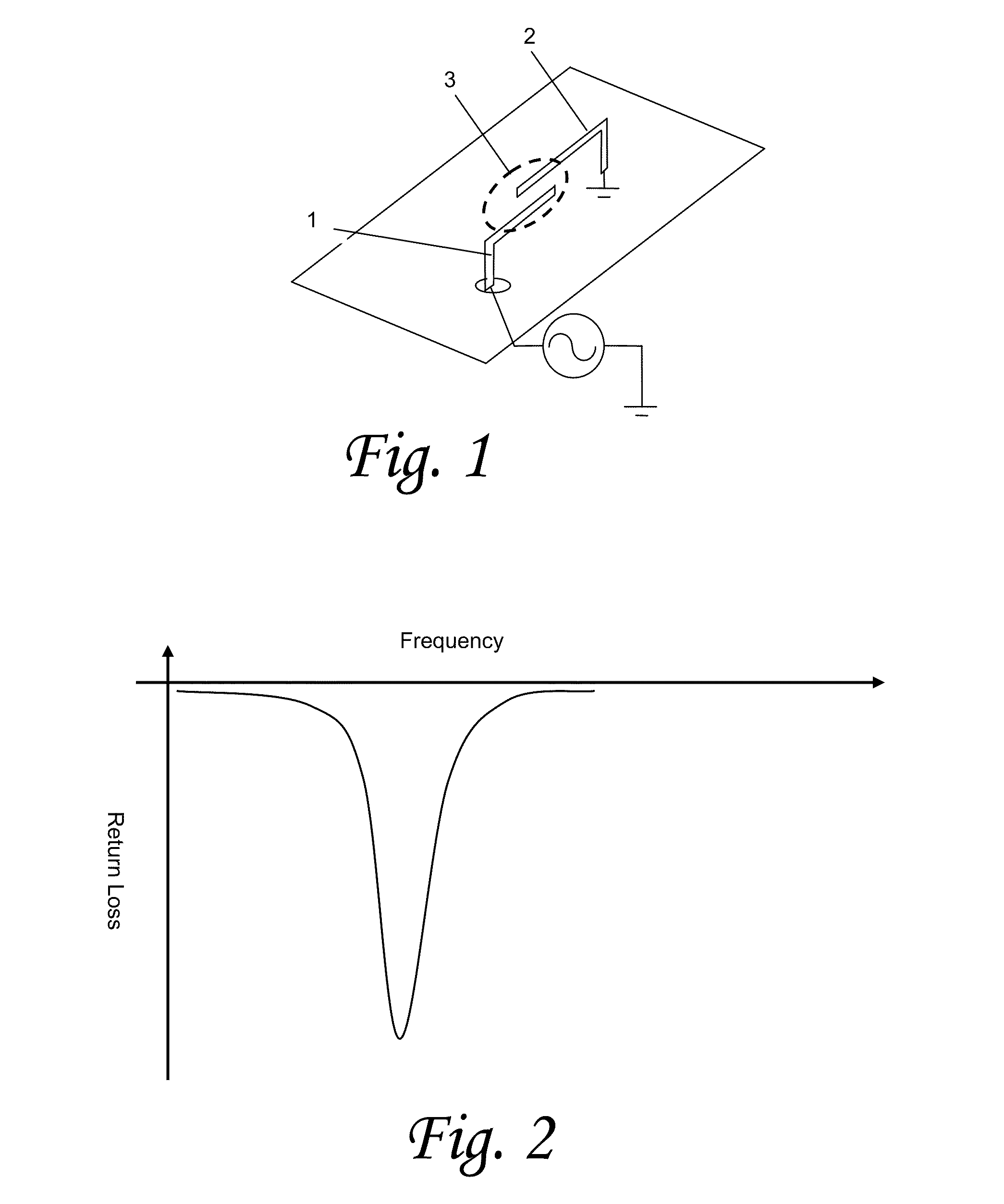
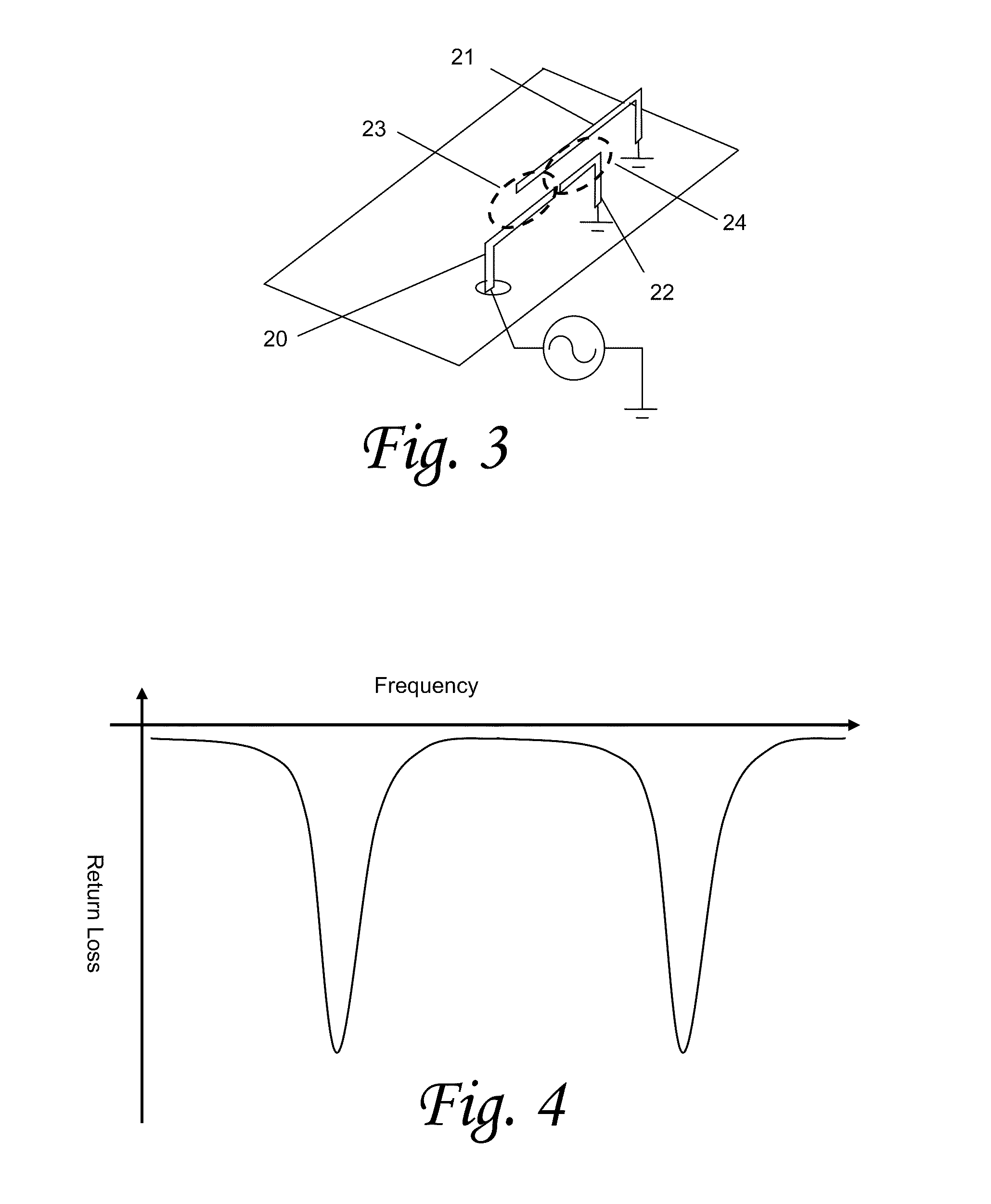
[0033]Embodiments of the present invention provide an active tuned loop-coupled antenna capable of optimizing an antenna over incremental bandwidths and capable of tuning over a large total bandwidth. The active loop element is capable of serving as the radiating element or an additional radiating element may also be coupled to this active loop. In various embodiments, multiple active tuned loops can be coupled together in order to extend the total bandwidth of the antenna. Such active components may be incorporated into the antenna structure to provide further extensions of the bandwidth along with increased optimization of ...


PUM


Abstract

An antenna having a driven element coupled to multiple additional elements to resonate at multiple frequencies. A magnetic dipole mode is generated by coupling a driven element to a second element, and additional resonances are generated by coupling additional elements to either or both of the driven or second element. One or multiple active components can be coupled to one or more of the coupled elements to provide dynamic tuning of the coupled or driven elements.

Description

FIELD OF THE INVENTION[0001]The present invention relates generally to the field of wireless communication. In particular, the present invention relates to antennas and methods of improving frequency response and selection for use in wireless communications.BACKGROUND OF THE INVENTION[0002]Commonly owned U.S. Pat. Nos. 6,677,915 filed Feb. 12, 2001, titled “SHIELDED SPIRAL SHEET ANTENNA STRUCTURE AND METHOD”; 6,906,667 filed Feb. 14, 2002, titled “MULTIFREQUENCY MAGNETIC DIPOLE ANTENNA STRUCTURES FOR VERY LOW PROFILE ANTENNA APPLICATIONS”; 6,900,773 filed Nov. 18, 2002, titled “ACTIVE CONFIGUREABLE CAPACITIVELY LOADED MAGNETIC DIPOLE”; and 6,919,857 filed Jan. 27, 2003, titled “DIFFERENTIAL MODE CAPACITIVELY LOADED MAGNETIC DIPOLE ANTENNA”; describe an Isolated Magnetic Dipole (IMD) antenna formed by coupling one element to another in a manner that forms a capacitively loaded inductive loop, setting up a magnetic dipole mode, the entire contents of which are hereby incorporated by r...

Claims


Application Information

Patent Timeline
Patent Type & Authority Applications(United States)
IPC IPC(8): H01Q1/36H01Q1/48
CPCH01Q7/005H01Q9/42H01Q9/16H01Q9/06H01Q19/005H01Q5/321H01Q5/328H01Q5/378H01Q5/385
Inventor HENG, CHEW CHWEEDESCLOS, LAURENTROWSON, SEBASTIANSHAMBLIN, JEFFREY
Owner HENG CHEW CHWEE
Why Eureka
Try Eureka