Directive Window Ablation Antenna with Dielectric Loading

a technology of dielectric loading and direct ablation, which is applied in the field of directional radiation pattern-based electrosurgical devices, can solve the problems of damage to healthy tissue, difficult to assess the extent, and too small or too hard to be punctured with ablation targeted lesions

Active Publication Date: 2011-02-10
TYCO HEALTHCARE GRP LP
View PDF38 Cites 57 Cited by
  • Summary
  • Abstract
  • Description
  • Claims
  • Application Information

AI Technical Summary

Problems solved by technology

Some ablation targeted lesions are too small or too hard to be punctured by an ablation probe.
With non-directional ablation probes, the ablation may radiate to both sides of the probe which may damage healthy tissue located on the non-tumor side of the

Method used


Image

  • Directive Window Ablation Antenna with Dielectric Loading
  • Directive Window Ablation Antenna with Dielectric Loading
  • Directive Window Ablation Antenna with Dielectric Loading

Examples


Embodiment Construction

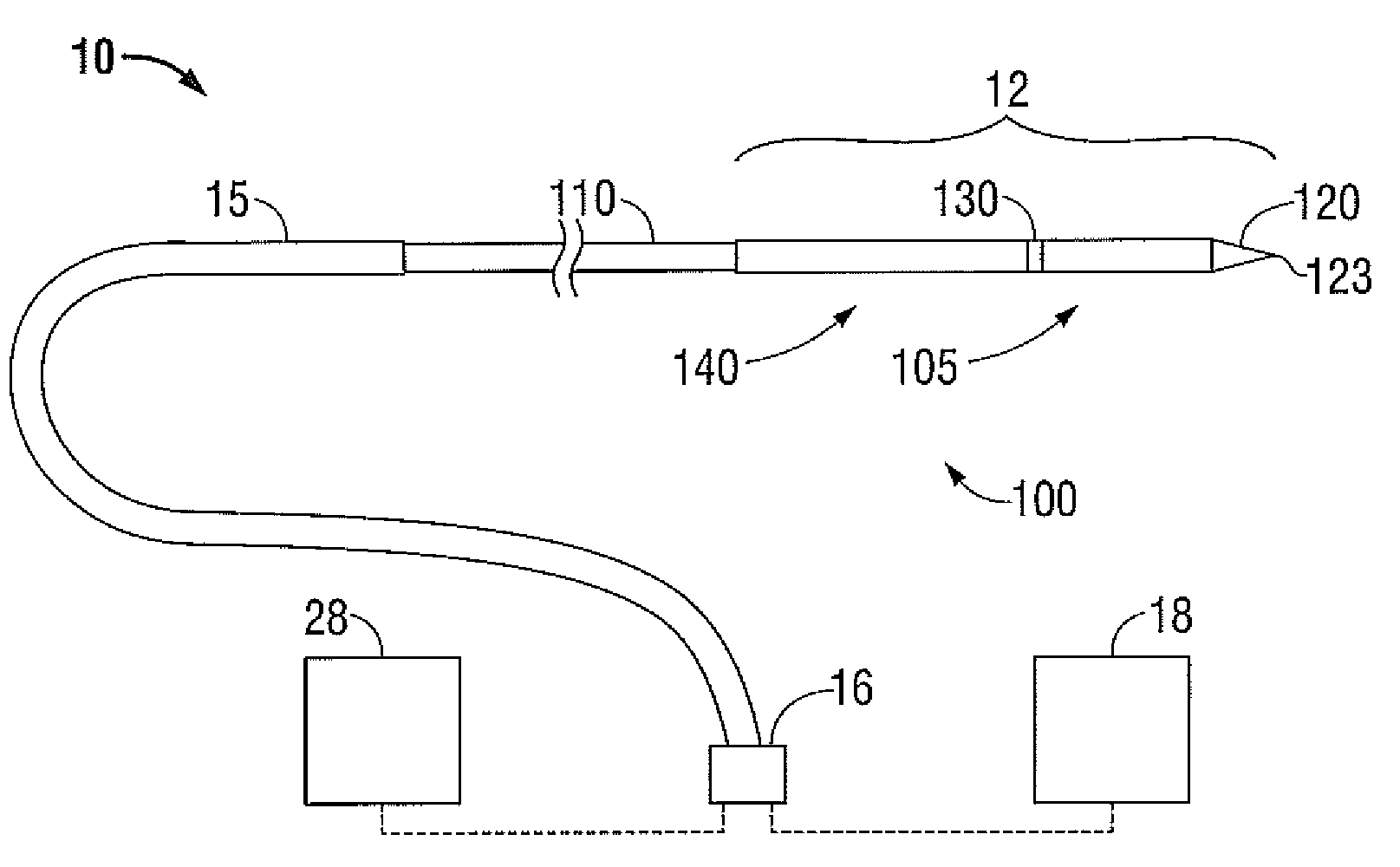
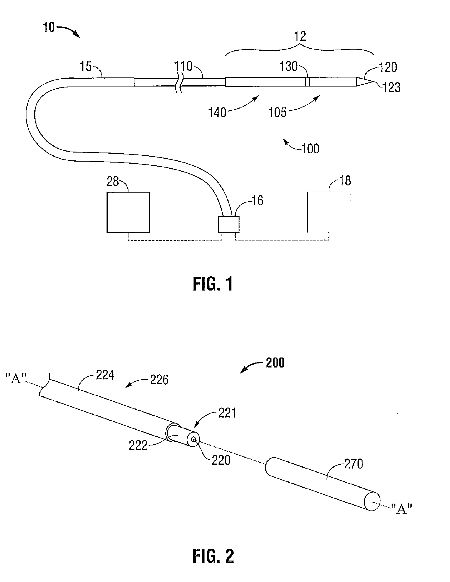
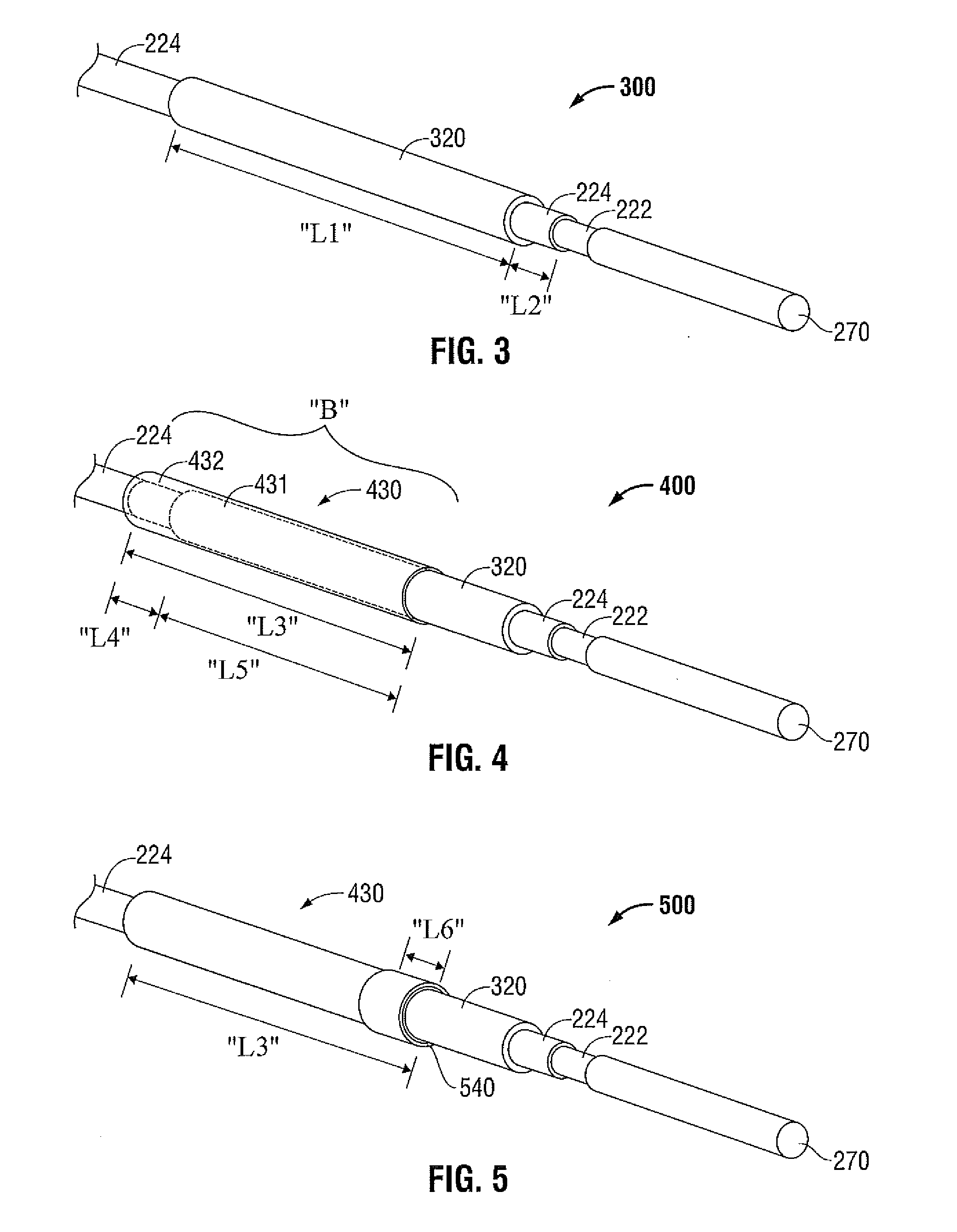
[0038]Hereinafter, embodiments of the presently disclosed electrosurgical device with a directional radiation pattern will be described with reference to the accompanying drawings. Like reference numerals may refer to similar or identical elements throughout the description of the figures. As shown in the drawings and as used in this description, and as is traditional when referring to relative positioning on an object, the term “proximal” refers to that portion of the apparatus that is closer to the user and the term “distal” refers to that portion of the apparatus that is further from the user.

[0039]Electromagnetic energy is generally classified by increasing energy or decreasing wavelength into radio waves, microwaves, infrared, visible light, ultraviolet, X-rays and gamma-rays. As it is used in this description, “microwave” generally refers to electromagnetic waves in the frequency range of 300 megahertz (MHz) (3×10⁸ cycles / second) to 300 gigahertz (GHz) (3×10¹¹ cycles / second). ...


PUM

PropertyMeasurementUnit
Dielectric polarization enthalpyaaaaaaaaaa
Electrical conductoraaaaaaaaaa
Transparencyaaaaaaaaaa

Abstract

An electrosurgical device for directing energy to a target volume of tissue includes a coaxial feedline having an inner conductor, an outer conductor coaxially disposed around the inner conductor, and a dielectric material disposed therebetween. An elongated electrically-conductive member is longitudinally disposed at a distal end of the inner conductor. A balun structure is disposed on the outer conductor. The device also includes an electrically-conductive cylinder coaxially disposed around a distal portion of the balun structure, and a dielectric structure disposed substantially adjacent to a distal end of the electrically-conductive cylinder, wherein the dielectric structure longitudinally extends from the distal end of the electrically-conductive cylinder to a distal end of the electrically-conductive member.

Description

BACKGROUND[0001]1. Technical Field[0002]The present disclosure relates to electrosurgical devices suitable for use in tissue ablation applications and, more particularly, to electrosurgical devices with directional radiation patterns.[0003]2. Discussion of Related Art[0004]Treatment of certain diseases requires the destruction of malignant tissue growths, e.g., tumors. Electromagnetic radiation can be used to heat and destroy tumor cells. Treatment may involve inserting ablation probes into tissues where cancerous tumors have been identified. Once the probes are positioned, electromagnetic energy is passed through the probes into surrounding tissue.[0005]In the treatment of diseases such as cancer, certain types of tumor cells have been found to denature at elevated temperatures that are slightly lower than temperatures normally injurious to healthy cells. Known treatment methods, such as hyperthermia therapy, heat diseased cells to temperatures above 41° C. while maintaining adjace...

Claims


Application Information

Patent Timeline
IPC IPC(8): A61B18/18A61B18/14
CPCA61B18/00A61B18/1477A61B18/18A61B2018/00011A61B2018/00053Y10T29/49117A61B2018/1425A61B2218/002A61B18/14A61B18/1487H05K13/00A61B2018/00577
Inventor BRANNAN, JOSEPH D.
Owner TYCO HEALTHCARE GRP LP
Why Eureka
Try Eureka