Shear Pin Activated Overhead Sign Bracket

a technology of overhead sign and shear pin, which is applied in the direction of stands/trestles, instruments, display means, etc., can solve the problem that the kelly device does not allow easy adjustment, and achieve the effect of surviving high wind loads

Inactive Publication Date: 2011-02-17
ROSABAL FELIX ANTONIO
View PDF5 Cites 2 Cited by
  • Summary
  • Abstract
  • Description
  • Claims
  • Application Information

AI Technical Summary

Benefits of technology

[0007]It is one of the main objects of the present invention to provide a sign bracket that will allow a sign and supporting structure to survive high wind loads, such as during a hurricane.
[0008]It is an object of the present invention to provide a sign bracket that allows the use of significantly lighter and more economical sign support structure because the sign will change profile at a predetermined wind speed and therefore will impart less stress onto the support structure.
[0009]It is another object of this invention to provide a uniform device that is scalable to effectively work with a wide variety of sign dimensions.
[0010]It is still another object of the present invention to provide a sign bracket that is easy to re-erect after a high wind event.
[0011]It is yet another object of this invention to provide such a device that is inexpensive to manufacture and maintain while retaining its effectiveness.

Problems solved by technology

None of them, however, includes a device that allows a highway sign to shift to the horizontal under heavy wind load to reduce the stress on both the sign and support structure while remaining easy to re-erect after risk of damaging winds subside.
However, it differs from the present invention because the Kelly device does not allow easy adjustment of the shear pressure exerted onto the sign to allow the sign to freely move and permits dangerous swinging of the sign after it begins to move.

Method used


Image

  • Shear Pin Activated Overhead Sign Bracket
  • Shear Pin Activated Overhead Sign Bracket
  • Shear Pin Activated Overhead Sign Bracket

Examples


Embodiment Construction

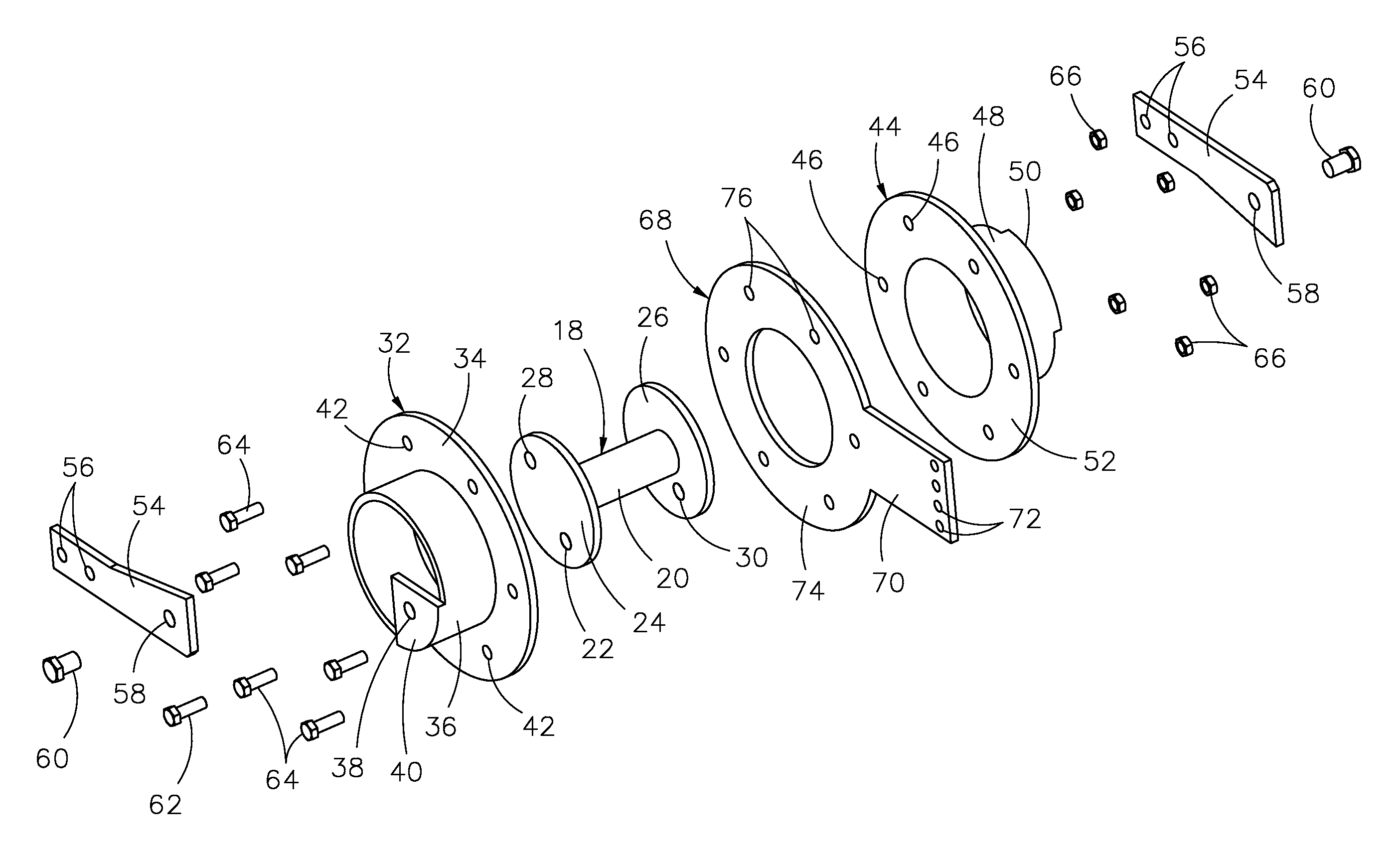
[0022]Referring now to the drawings, where the present invention is generally referred to with numeral 10, it can be observed that it basically includes a hub assembly 18, a drum assembly 32, a drum assembly 44 and a plate assembly 68.

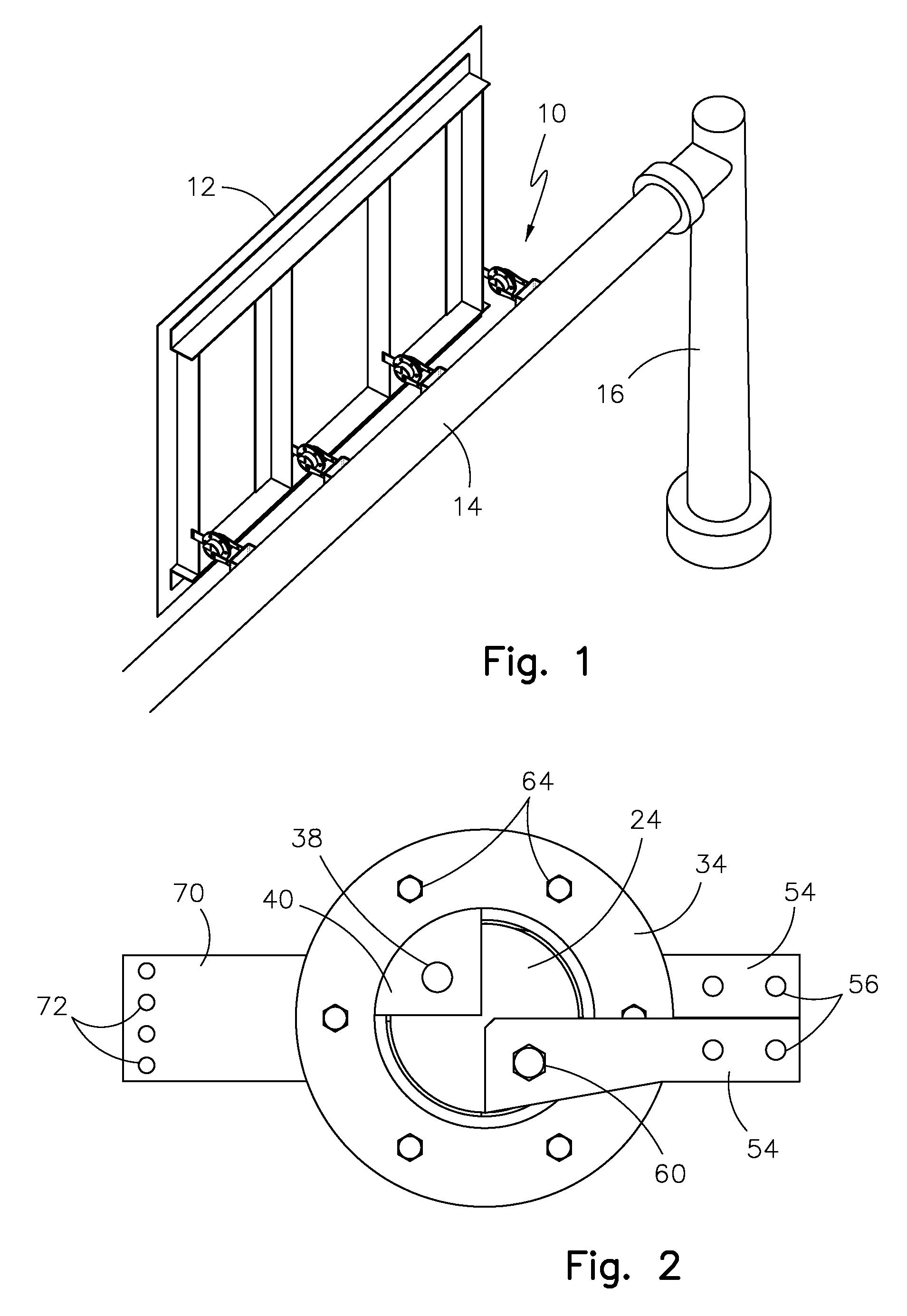
[0023]FIG. 1 shows the device 10 as it could be in actual use to support a sign 12. Overhead highway signage is often displayed over a roadway to provide navigational information to passing motorists. The present invention relates to brackets that connect a sign 12 to a support structure 14. A typical configuration includes a vertical support post 16 affixed to a horizontal support post 14. The present invention is an improved bracket 10 that connects the sign 12 to the horizontal support post 16. In some configurations two vertical support posts 16 connect at each end of the horizontal support bar 14 to span the roadway below and provide for a more robust sign support structure.

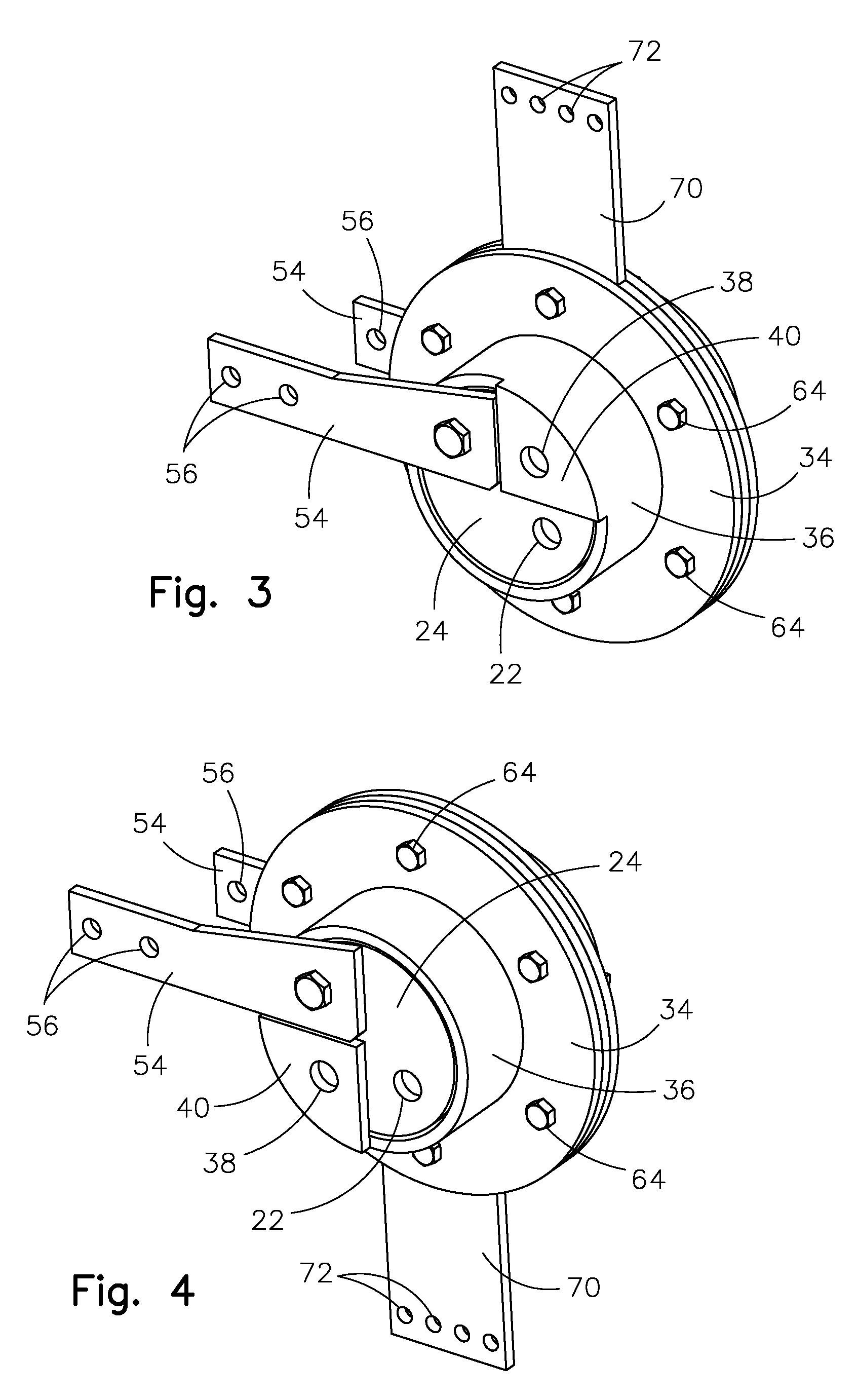
[0024]Now referring to FIGS. 2, 3 and 4 where the device is shown assemble...


PUM


Abstract

A sign bracket for over-road highway signs and other signs. The bracket comprised of a first assembly attached to the sign and a second assembly attached to a support structure. A shear pin is provided to prevent relative movement between the first assembly and second assembly in its normal state. When sufficient pressure is exerted on the sign torque is imparted onto the first assembly relative to the second assembly and the shear pin shears and the first assembly is freed to rotate approximately ninety degrees in either direction to relative to the torque. The sign is essentially laid flat either face up from wind force striking the face of the sign or face down from wind striking the rear of the sign. When the sign is laid flat it produces substantially reduced wind resistance and the support structure remains intact. The sign may then easily re-erected by insertion of a new shear pin.

Description

BACKGROUND OF THE INVENTION[0001]1. Field of the Invention[0002]The present invention relates to sign brackets, and more particularly, to highway overhead sign brackets that are capable of withstanding high wind load forces by changing the angle of incidence of the wind relative to the sign.[0003]2. Description of the Related Art[0004]Several designs for sign brackets have been designed in the past. None of them, however, includes a device that allows a highway sign to shift to the horizontal under heavy wind load to reduce the stress on both the sign and support structure while remaining easy to re-erect after risk of damaging winds subside.[0005]Applicant believes that the closest reference corresponds to U.S. Pat. No. 4,503,631 issued to Kelly. However, it differs from the present invention because the Kelly device does not allow easy adjustment of the shear pressure exerted onto the sign to allow the sign to freely move and permits dangerous swinging of the sign after it begins ...

Claims


Application Information

Patent Timeline
Patent Type & Authority Applications(United States)
IPC IPC(8): G09F15/00G09F7/00
CPCG09F7/20G09F2007/1817G09F15/005G09F15/0037
Inventor ROSABAL, FELIX ANTONIO
Owner ROSABAL FELIX ANTONIO
Why Eureka
Try Eureka