
Touch sensor device and pointing coordinate determination method thereof

a technology of pointing coordinate and sensor device, which is applied in the direction of instruments, computing, electric digital data processing, etc., can solve the problems of difficult to perform user interface operations intended by four persons, the plurality of touch objects may not be individually recognized at the same time, and the user demands may not be satisfied

Inactive Publication Date: 2011-02-17
ATLAB INC
View PDF11 Cites 76 Cited by
  • Summary
  • Abstract
  • Description
  • Claims
  • Application Information

AI Technical Summary

Benefits of technology

[0068]A touch sensor device according to the present invention can use touch information regarding touch strength of a touch object as well as a simple touch thereof, such that a pointer coordinate recognition algorithm and coordinate determination method of further various pointing devices are possible.
[0069]In motion environments of the pointing devices, a pointer can be prevented from being shaken due to repeated vibration or noise and user interface operations intended by a plurality of users can be performed. When touch means is a finger, a pointer can move to a target region by placing the pointer at a finger end.

Problems solved by technology

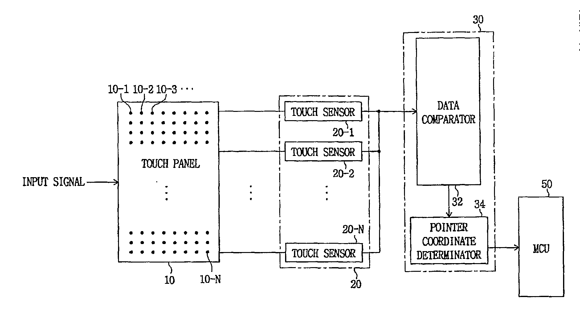
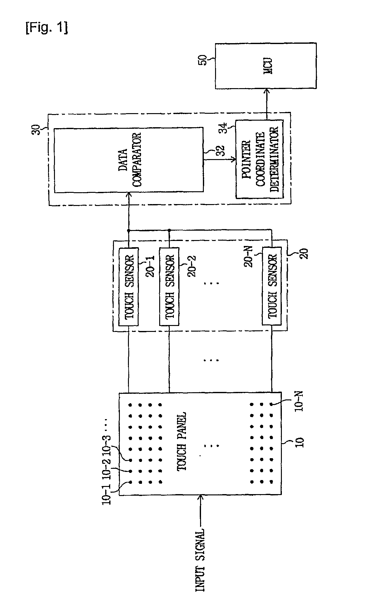
However, when a plurality of objects touch the touch panel 10, the above-described touch sensor device according to the prior art synthetically recognizes according to characteristics of matrix circuitry without individually recognizing the touch objects and outputs coordinates of one position irrespective of the number of touch objects, such that there is a problem in that the plurality of touch objects may not be individually recognized at the same time.
For example, when four persons at a tablet PC are located at top, bottom, left, and right positions of the touch panel 10 and simultaneously touch the touch panel 10 with their fingers, the number of touch fingers of the persons, geometric centers of the touch fingers, and positions touched by the persons are not individually recognized and motions of the touch fingers and movement directions thereof are not individually recognized, such that it is difficult to perform user interface operations intended by the four persons.
However, since the touch sensor device according to the prior art has a simple method using a connection of conductors conventionally configured with two layers, there is a problem in that user demands may not be satisfied due to limitations in applying various algorithms of pointer coordinate recognitions and coordinate determining methods further structurally stabilized.

Method used


Image

  • Touch sensor device and pointing coordinate determination method thereof
  • Touch sensor device and pointing coordinate determination method thereof
  • Touch sensor device and pointing coordinate determination method thereof

Examples


Embodiment Construction

[0078]Hereinafter, a touch sensor device and a pointing coordinate determination method thereof according to the present invention will be described with reference to the accompanying drawings.

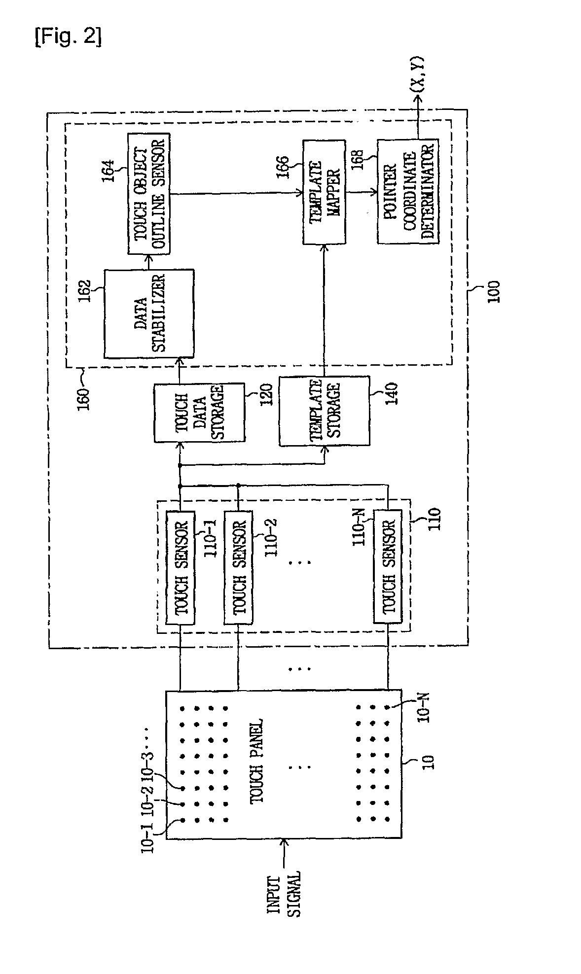
[0079]FIG. 2 is a schematic block diagram of the touch sensor device according to the present invention, which includes a touch panel 10 and a touch sensing and data processing unit 100. The touch panel 10 is configured with a plurality of touch electrodes 10-1 to 10-N, and the touch sensing and data processing unit 100 is provided with a touch sensing unit 110, a touch data storage 120, a template storage 140, and a touch data processor 160, wherein the touch data processor 160 includes a data stabilizer 162, a touch object outline sensor 164, a template mapper 166, and a pointer coordinate determinator 168.

[0080]The functions of blocks of the touch sensor device according to the present invention will be described with reference to FIG. 2.

[0081]The touch panel 10 has the plurality of touch e...


PUM


Abstract

Provided are a touch sensor device and a pointing coordinate determination method thereof. The touch sensor device includes a touch panel, a touch sensing unit that receives a touch signal, senses touch information according to a simple touch or touch strength of a touch object, and outputs an electrical signal, a touch data storage that stores touch data in response to the electrical signal, a template storage that pre-stores templates for various outlines of the touch object in response to the electrical signal, and a touch data processor that senses an outline of the touch object according to a distance difference related to the touch object by receiving the touch data, and determines pointer coordinates of a pointing device by receiving and mapping a stored template of the touch object.

Description

TECHNICAL FIELD[0001]The present invention relates to a touch sensor device, and more particularly, to a touch sensor device capable of stably and variously recognizing and determining pointer coordinates and a pointing coordinate determining method thereof.BACKGROUND ART[0002]As one of data input devices, a touch pad has sensing points arranged in a matrix pattern on a plane. Since the touch pad may sense a position pressed by a user and a movement direction of a contact point, it is being widely used in place of a mouse. There are various types of touch pads including a touch pad in which electrical switches are arranged on the plane or, a touch pad in which a capacitive sensor, a resistive sensor, a surface wave sensor, or an optical sensor is arranged on the plane.[0003]To adjust the motion of a cursor in a laptop computer or the like, a touch panel configured with a plurality of touch pads using the capacitive sensor is usually used. A surface of the touch panel is covered with...

Claims


Application Information

Patent Timeline
IPC IPC(8): G06F3/044
CPCG06F3/0416G06F3/04166G06F3/044
Inventor LEE, SANG-JINJOUNG, CHUL-YONGLEE, BANG-WON
Owner ATLAB INC
Learn More