
Remote Control Water Valving System for Shower or Sink

Inactive Publication Date: 2009-10-22
CONNORS PAUL E
View PDF6 Cites 61 Cited by
  • Summary
  • Abstract
  • Description
  • Claims
  • Application Information

AI Technical Summary

Benefits of technology

[0018]The disclosed system provides a novel and easily engageable set of components for the temporary cessation of already flowing water in an outflow component such as a shower head in a shower or a faucet in a sink. Allowing users to easily initiate a cessation of flowing water, with a simple touch of an area of their body to a controller, encourages use since they need not see it or have to employ a hand or finger. Thus, elimination of water and energy waste is encouraged during periods the user is occupied in a non-water task such as lathering, shampooing, or brushing their teeth, since the user need not employ the dexterity of a hand or finger to cease water flow. This is an important consideration when the eyes may not be opened such as when shampooing.
[0020]In use, a power supply communicates with a controller which acts to communicate power to an electrically activated valve during periods of activation initiated by depression of the button of the remote control. The valve will move between an open position allowing water flow and a closed position ceasing water flow. The controller may require continuous pressure by a body part, somewhat like a deadman's switch, or the controller may have a flip-flop type switching circuits that alternatively energizes and de-energizes the communication of power to the valve controlling water flow. The device would thus cease the flow of already running water, and immediately restart the flow using a simple activation of the remote control component mounted on a wall or in the case of a sink, a cabinet.
[0021]In use, the user while lathering or shampooing when the user cannot easily see, or while brushing their teeth or lathering their face at a sink, an easy cessation of water flow is provided by a simple contact with a contact surface of the remote control component. This contact by a body part, will cause an RF, sonic, hydraulic, pneumatic, or optical signal, to be communicated to a controller which will act to energize the water valve to cease flow or in the case of an electronic signal, the water valve itself may be the control if it is already wired to move to the opposite position when signaled electronically.
[0023]Consequently, the user can easily, without the aide of eyesight, and with some body part, activate the remote control component to cause a cessation of the water flow when they are occupied in a fashion where water is not needed. A second contact with the contact area on the control would restart water flow. This would occur for instance in the case of lathering or shampooing in the shower. Water and energy are thus saved for this duration. The user need not be able to see the remote control component to activate it to turn the water off and on, thereby encouraging use.

Problems solved by technology

Water for domestic use is becoming ever-harder to provide with an expanding population.
In coming years however, and currently in dry venues such as Southern California, the supply is already insufficient to meet the growing population of people and the new homes constructed for that increased population.
Further exacerbating the shortages is the ongoing drought in the Western States which appears to be cyclical and will as such return again once the current drought abates.
More showers, sinks, and such, will continue to put additional perpetual strain on the finite water supply available.
Consequently, reducing water usage not only saves the water itself, but also conserves valuable energy resources and resulting energy costs.
During normal water usage by individuals there are times when the water is uselessly running down the drain.
The same problem of water and energy waste arises with facial washing or tooth brushing at a sink, or while hand-washing dishes.

Method used


Image

  • Remote Control Water Valving System for Shower or Sink
  • Remote Control Water Valving System for Shower or Sink
  • Remote Control Water Valving System for Shower or Sink

Examples


Embodiment Construction

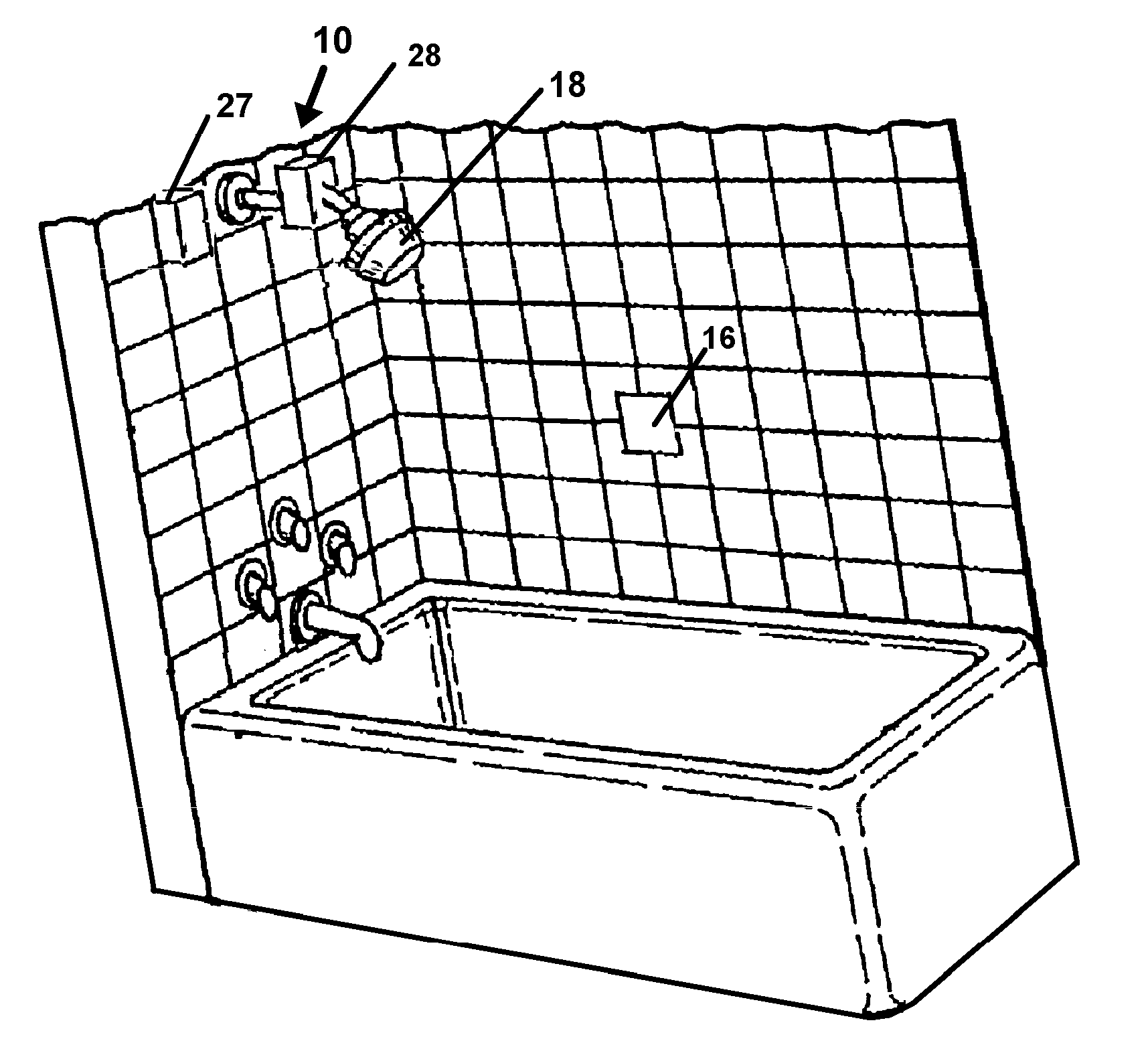
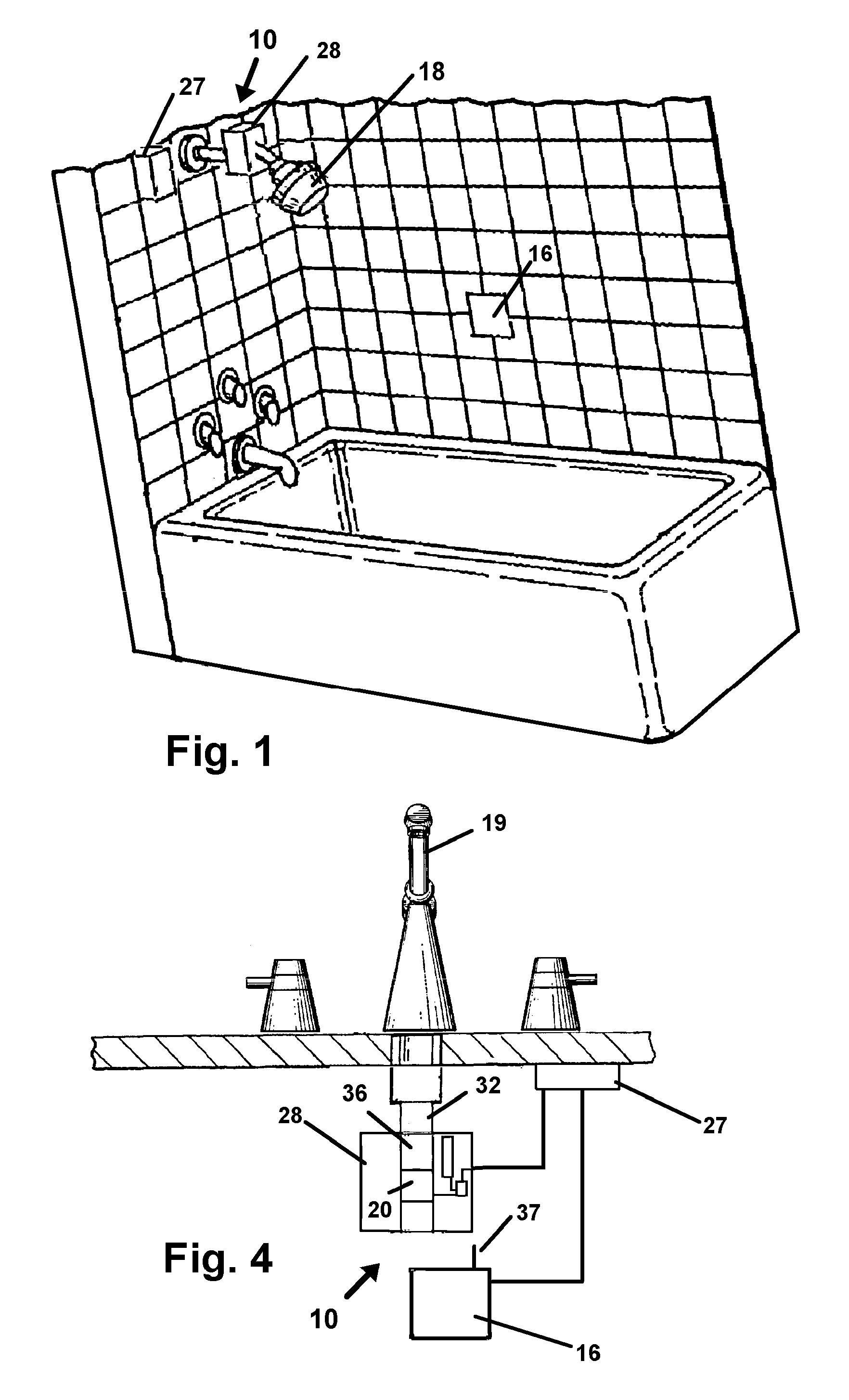
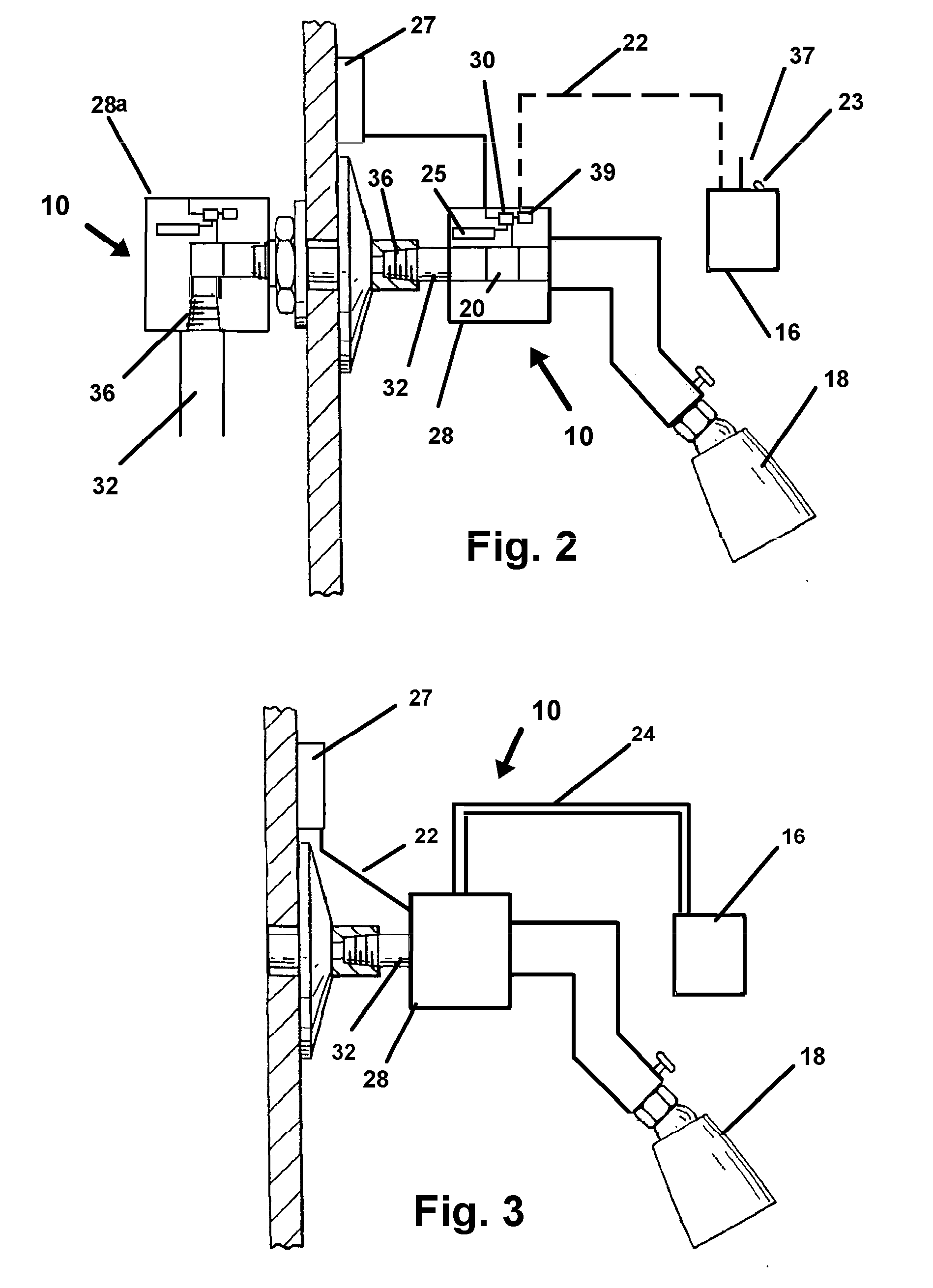
[0028]Referring now to the drawings, FIGS. 1-4 where similar components are identified in one or more of the drawings with the same numerals, the disclosed device 10 provides a novel system for the temporary cessation of already-flowing water in an outflow component such as a shower head 18 in a shower 12 or a faucet 19 in a sink 14 (FIG. 4). During activation of the device 10 a user, need not employ any special dexterity or even their eyesight since the device 10 employs a control component 16 adapted with a contact area of sufficient size to provide a means for tactile location without eyesight. Currently a size from two square inches in size to thirty six square inches in size have proven to work well to allow the user to “find” the contact surface on the control component 16 without the aid of their eyesight. A six inch by six inch tile would work especially well on shower installations having this size tile as it would blend into the wall if positioned correctly, and provide th...


PUM


Abstract

A remote controlled valve for cessation of water flow from an outflow component such as a showerhead or faucet during periods where water flow is not required by the user to provide for water conservation. The device features a remote control having a large contact area for contact with the user's arm or leg or hip to allow for activation without the use of their hands and fingers. The large size also renders the remote control unit easily located by sense of touch and without the user's eyesight to encourage use by users who might otherwise be concerned about reinitiating water flow during shampooing or while using he device on a sink with their hands wet or occupied.

Description

FIELD OF THE INVENTION[0001]This application claims priority to U.S. Provisional Patent Application No. 61 / 047085 filed Apr. 22, 2008 and which is incorporated herein in its entirety by reference. The disclosed invention relates to water flow control. More particularly it relates to a system and method providing for a user operated remote control which may be activated by contact with any part of the body, to temporarily cease the flow of water already running in a shower or sink.BACKGROUND OF THE INVENTION[0002]Water for domestic use is becoming ever-harder to provide with an expanding population. Over many years dams providing reservoirs and increased drilling for ground water have managed to provide water to an ever growing population in the United States and the industrialized world. Consequently, while shortages occur due to drought and other supply interruption, such shortages have not been too severe.[0003]In coming years however, and currently in dry venues such as Southern ...

Claims


Application Information

Patent Timeline
IPC IPC(8): F16K31/02
CPCE03C1/057F16K51/00F16K31/02F16K19/006
Inventor CONNORS, PAUL E.
Owner CONNORS PAUL E
Learn More