Press-in contact having a base, a contact pin and a second pin

a press-in contact and contact pin technology, applied in the field of press-in contact, can solve the problems of electrical short circuit on the circuit board, damage to the copper sleeve, etc., and achieve the effect of simple and accurate positioning and simple press-in conta

Active Publication Date: 2011-02-17
ROBERT BOSCH GMBH
View PDF16 Cites 7 Cited by
  • Summary
  • Abstract
  • Description
  • Claims
  • Application Information

AI Technical Summary

Benefits of technology

[0006]An object of the present invention is to provide a simple press-in contact. In particular, an aid is to be provided that renders possible simple and accurate positioning between circuit board and a contact pin disposed in a housing.
[0008]In an advantageous manner, the centering pin has, at the level of and over a length of the press-in portion of the contact pin, a smaller circumference than the press-in portion. In that manner a mechanical over-determination of the circuit board in the pressed-in state is reliably avoided.
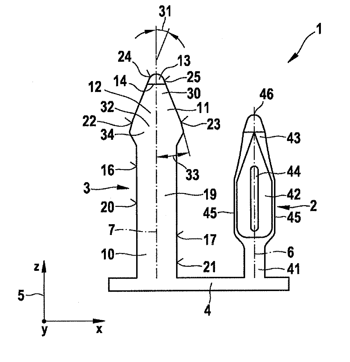
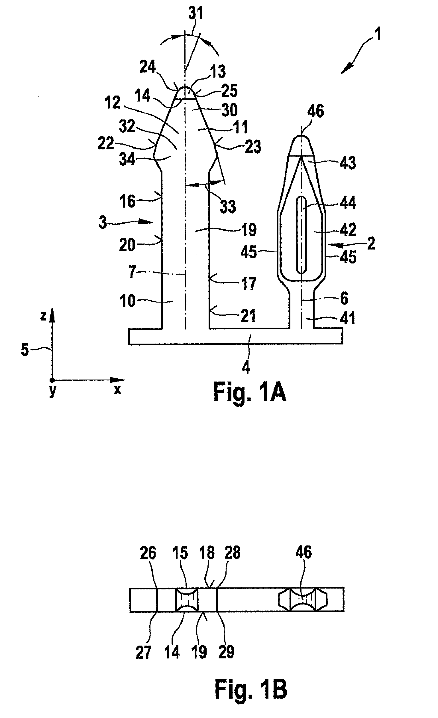
[0009]In a simple manner, the second pin is arrow-shaped with a cuboidal shaft and a tip. After the widest point of the pre-centering pin, the pre-centering pin tapers toward the base and forms the shaft. The shaft is elongate and of small circumference. As a result, after the pressing-in procedure, the circuit board is not over-determined laterally. The widest point of the pre-centering pin has a slight amount of clearance inside the pre-centering bore, and therefore the circuit board is not over-determined laterally at the beginning of the pressing-in procedure. The press-in contact is also referred to as an insert, which may be inserted into a mold and thereafter encased in plastics material, that is, cast into a plastics housing. The position of the circuit board within the housing is determined merely by the press-in pin. By virtue of the fact that the press-in contact and the housing are manufactured separately, a simple undercutting of the centering pin is made possible.
[0013]In a simple manner, a diameter of the second opening is 1.2 times to two times the diameter, especially 1.3 times the diameter, of the first opening. That makes simple centering of the circuit board possible.

Problems solved by technology

If the circuit board and the housing are not accurately positioned relative to each other during the pressing-in procedure, damage to the copper sleeve occurs.
Metal particles that have been chipped off cause electrical short-circuits on the circuit board.

Method used


Image

  • Press-in contact having a base, a contact pin and a second pin
  • Press-in contact having a base, a contact pin and a second pin
  • Press-in contact having a base, a contact pin and a second pin

Examples


Embodiment Construction

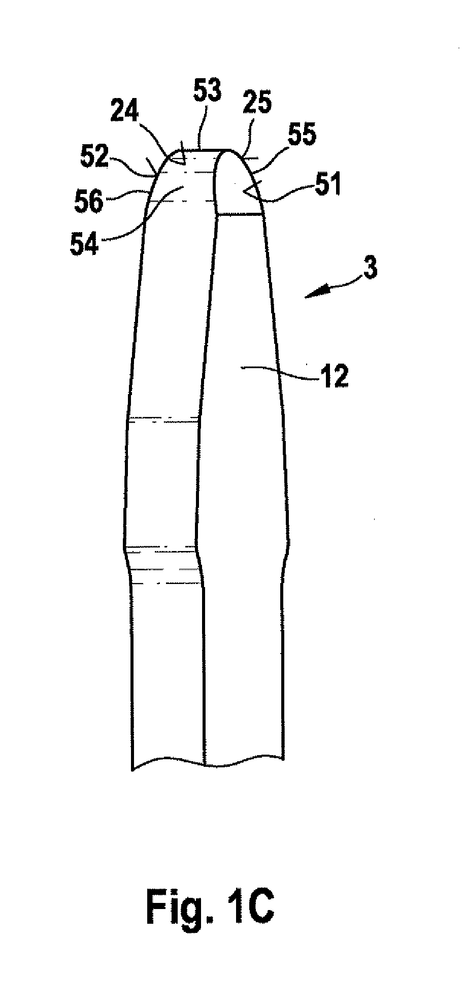
[0047]FIGS. 1A and 1B show a press-in contact 1 having a contact pin 2 and a second pin 3 on a base 4 in a coordinate system 5 having an x-, a y- and a z-axis. The second pin 3 acts as a centering pin 3 and is also referred to as a pre-centering pin 3 or, in short, as centering pin 3. The press-in contact 1 is punched out of sheet metal and then stamped. The sheet metal is of a constant thickness. A depth of press-in contact 1 is given by the thickness of the sheet metal, is constant and extends in the y-direction. A length and a width of contact pin 2, centering pin 3 and base 4 are obtained as a result of the punching operation and are variable. Contact pin 2 and centering pin 3 are arranged parallel to each other and extend in the z-direction. Contact pin 2 is formed symmetrically with respect to a longitudinal axis 6 extending in the z-direction. Centering pin 3 is formed symmetrically with respect to a second longitudinal axis 7 extending in the z-direction. The width of contac...


PUM

PropertyMeasurementUnit
angleaaaaaaaaaa
angleaaaaaaaaaa
angleaaaaaaaaaa

Abstract

A press-in contact having a base, a contact pin and a second pin which extends parallel to the contact pin. The second pin projects beyond the contact pin and has a greatest circumference at the same level as a tip of the contact pin. Simple and accurate positioning between a circuit board and a contact pin disposed in a housing is made possible by the second pin which acts as a pre-centering pin.

Description

FIELD OF THE INVENTION[0001]The present invention relates to a press-in contact having a base, a contact pin and a second pin which extends parallel to the contact pin, a housing having a contact pin and a second pin or two further pins which extend parallel to the contact pin, a method for inserting a circuit board into a housing having a contact pin and a second pin which extends parallel to the contact pin, and a circuit board having at least two openings of which at least a first opening has a contact sleeve for receiving a press-in pin.BACKGROUND INFORMATION[0002]German Patent Application No. DE 102 23 382 A1 describes a press-in contact with a press-in base and with at least two contact pins which are referred to therein as press-in pins. Provided in the press-in base there is a slot-shaped recess disposed between the two press-in pins and extending from the underside of the press-in base. That ensures a resilient behavior when the press-in contact having at least two press-in...

Claims


Application Information

Patent Timeline
Patent Type & Authority Applications(United States)
IPC IPC(8): H01R12/00H01R13/02H01R13/42H05K3/00H01R12/55H01R12/58
CPCY10T29/49128H01R12/585
Inventor LUDWIG, RONNY
Owner ROBERT BOSCH GMBH
Why Eureka
Try Eureka