
Posterior stabilizer

a stabilizer and posterior technology, applied in the field of spinal prosthesis, can solve the problems of spinal instability, severe lower back pain, and inability to replace degenerative discs,

Inactive Publication Date: 2011-02-17
SPINADYNE
View PDF102 Cites 13 Cited by
  • Summary
  • Abstract
  • Description
  • Claims
  • Application Information

AI Technical Summary

Benefits of technology

[0008]The present invention advantageously provides a method and system for spinal stabilization. In particular, the spinal stabilization system may include both fixed and movable components providing a minimum reduction in the natural movement of a first motion segment of the spinal column while preventing or restricting movement in a second motion segment of the spinal column when implanted.

Problems solved by technology

While many individuals may simply experience minor sprains or strains that may be somewhat limiting, numerous individuals may develop severe lower back pain caused by inflammatory changes in the lumbar disc associated with such changes.
However, the replacement of a degenerative disc may not suffice, as the facet joint components of the spinal column may still be a source of discomfort and / or limited mobility.
This often makes the spine unstable, requiring stabilization of the spine after the decompression.
A posterior dynamic stabilization device is typically attached to pedicle screws inserted in to the vertebrae, however, conventional devices are limited in their allowable range of motion and results may vary from patient to patient.

Method used


Image

  • Posterior stabilizer
  • Posterior stabilizer
  • Posterior stabilizer

Examples


Embodiment Construction

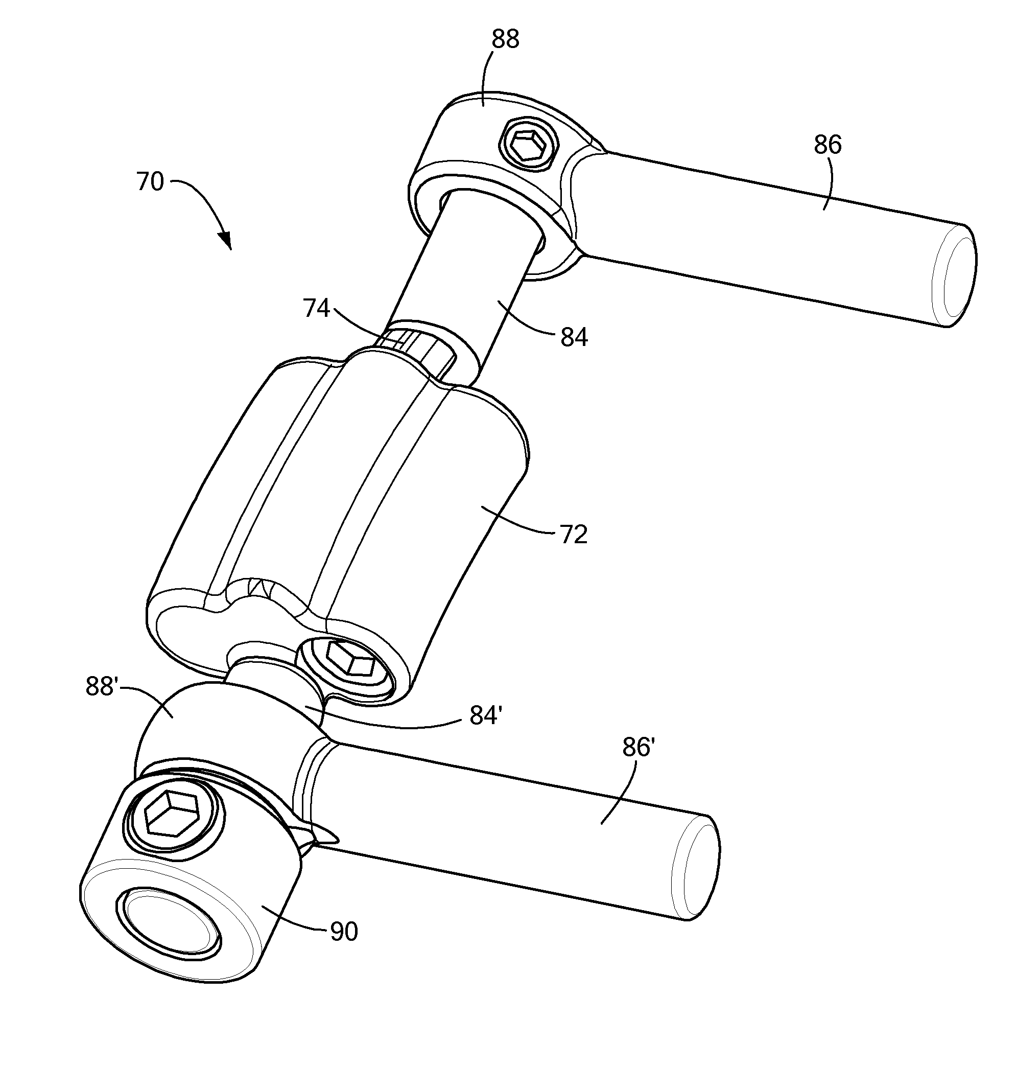
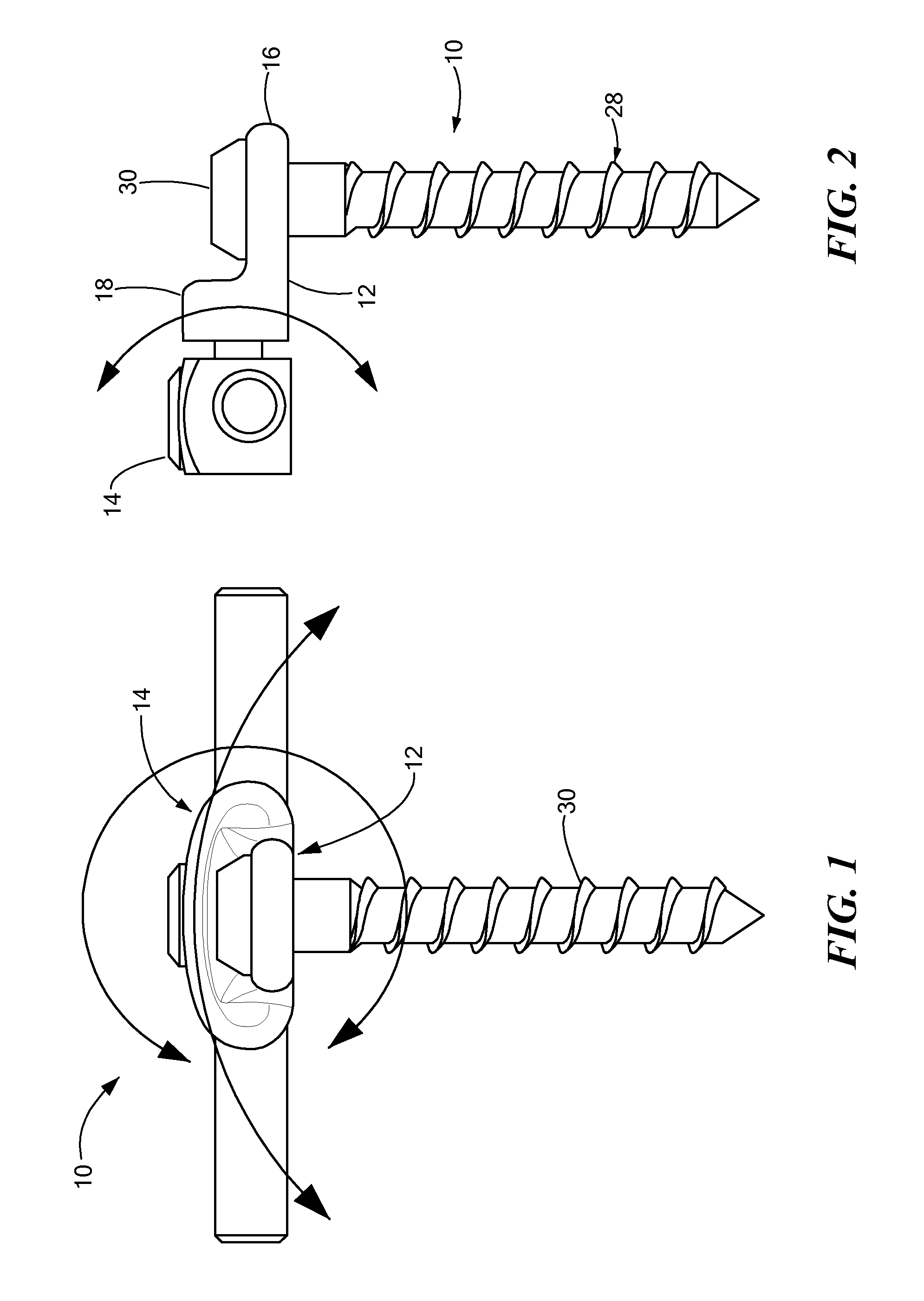
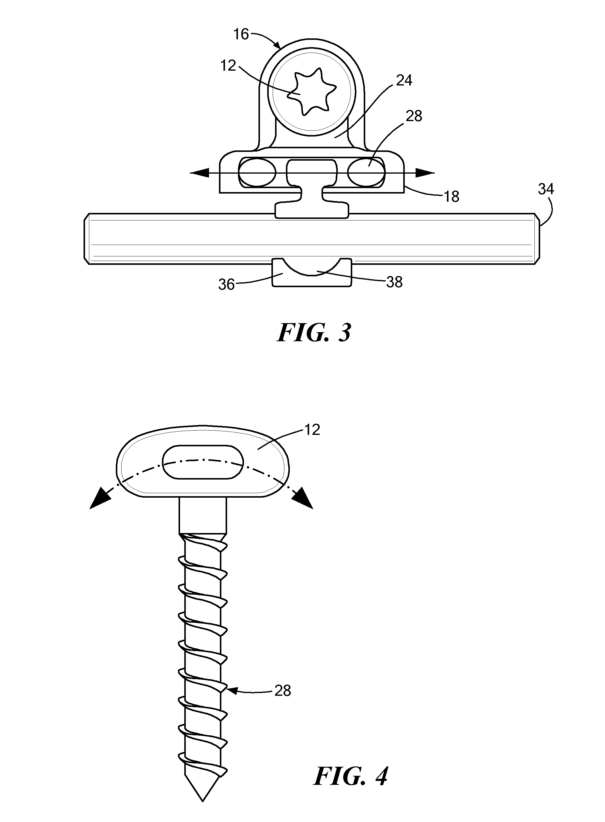
[0037]The present invention includes a spinal stabilization system implantable on or about one or more spinal segments spanning one or more intervertebral discs and vertebrae. In particular, the spinal stabilization system may include several stabilizing components having varying ranges of movement and / or degrees-of-freedom to selectively provide varying ranges of motion for adjacent portions of a spinal segment. By combining one or more of the following described components about a particular vertebral site (which may include one or more intervertebral discs, vertebrae, and facet joints), a desired range of spinal motion and / or level of fixation may be selected and achieved.

[0038]Now referring to the figures, in which like reference designators refer to like elements, there is shown in FIGS. 1-4 an embodiment of a dynamic connector constructed in accordance with the principles of the present invention and generally designated as “10.” The illustrated dynamic connector 10 may genera...


PUM


Abstract

A dynamic hybrid stabilization system having a plurality of affixation elements coupled to a spinal segment having at least two intervertebral spaces, each affixation element having a medially extending connector element. A plurality of dynamic stabilization devices having an adjustable range of motion and being spaced medially from the affixation elements is included, each dynamic stabilization device being coupled to at least one of the connector elements and including an attachment element spanning at least one intervertebral space, such that each dynamic stabilization device and the connector element when coupled together span at least two intervertebral spaces.

Description

CROSS-REFERENCE TO RELATED APPLICATION[0001]This application is related to and claims priority to U.S. Provisional Patent Application Ser. No. 61 / 179,873, filed May 5, 2009, entitled POSTERIOR STABILIZER, the entirety of which is incorporated herein by reference.STATEMENT REGARDING FEDERALLY SPONSORED RESEARCH OR DEVELOPMENT[0002]n / aFIELD OF THE INVENTION[0003]The present invention relates to spinal prostheses, and in particular, a method and system for spinal stabilization, including prostheses and components implantable on or about a spinal segment.BACKGROUND OF THE INVENTION[0004]A significant portion of the population experiences pain or discomfort resulting from spinal injuries or degenerative conditions in and around the vertebral discs. While many individuals may simply experience minor sprains or strains that may be somewhat limiting, numerous individuals may develop severe lower back pain caused by inflammatory changes in the lumbar disc associated with such changes.[0005]A...

Claims


Application Information

Patent Timeline
Patent Type & Authority Applications(United States)
IPC IPC(8): A61B17/70
CPCA61B17/701A61B17/7023A61B17/7004A61B17/7041A61B17/7025
Inventor FERNANDEZ, JOSEREDMOND, KEVIN
Owner SPINADYNE
Learn More