Wiring and composite wiring

a technology of composite wiring and wires, applied in the direction of waveguides, cables with twisted pairs/quadruples, electrical appliances, etc., can solve the problem of signal attenuation during transmission

Inactive Publication Date: 2011-02-24
IBIDEN CO LTD +4
View PDF5 Cites 231 Cited by
  • Summary
  • Abstract
  • Description
  • Claims
  • Application Information

AI Technical Summary

Benefits of technology

[0015]According to the present invention, a gigahertz band high frequency signal can be suitably transmitted.

Problems solved by technology

However, because DC resistance (R0) and dielectric loss (G0) exist in the transmission line, the signal attenuates during transmission.

Method used


Image

  • Wiring and composite wiring
  • Wiring and composite wiring
  • Wiring and composite wiring

Examples


Embodiment Construction

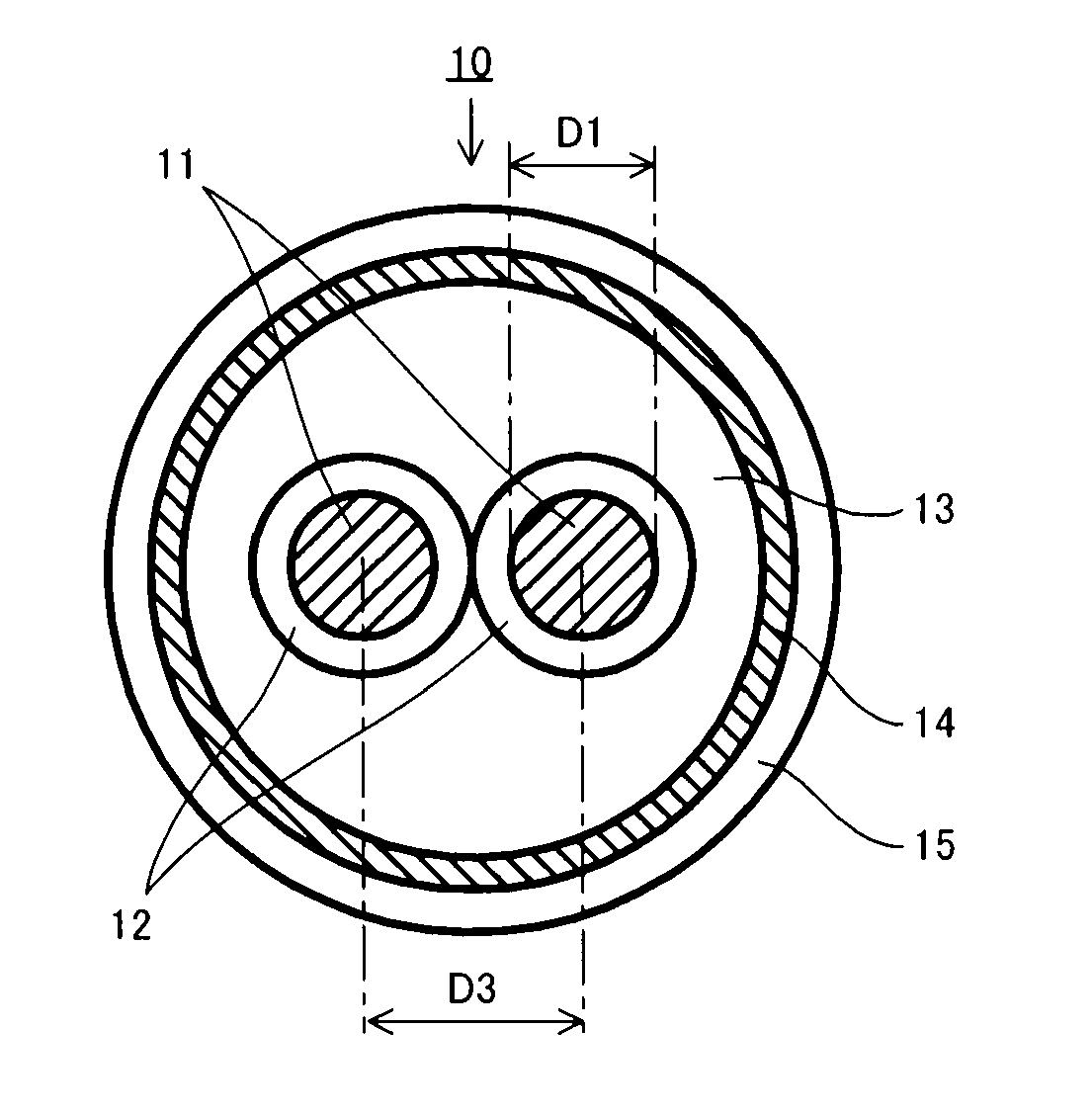
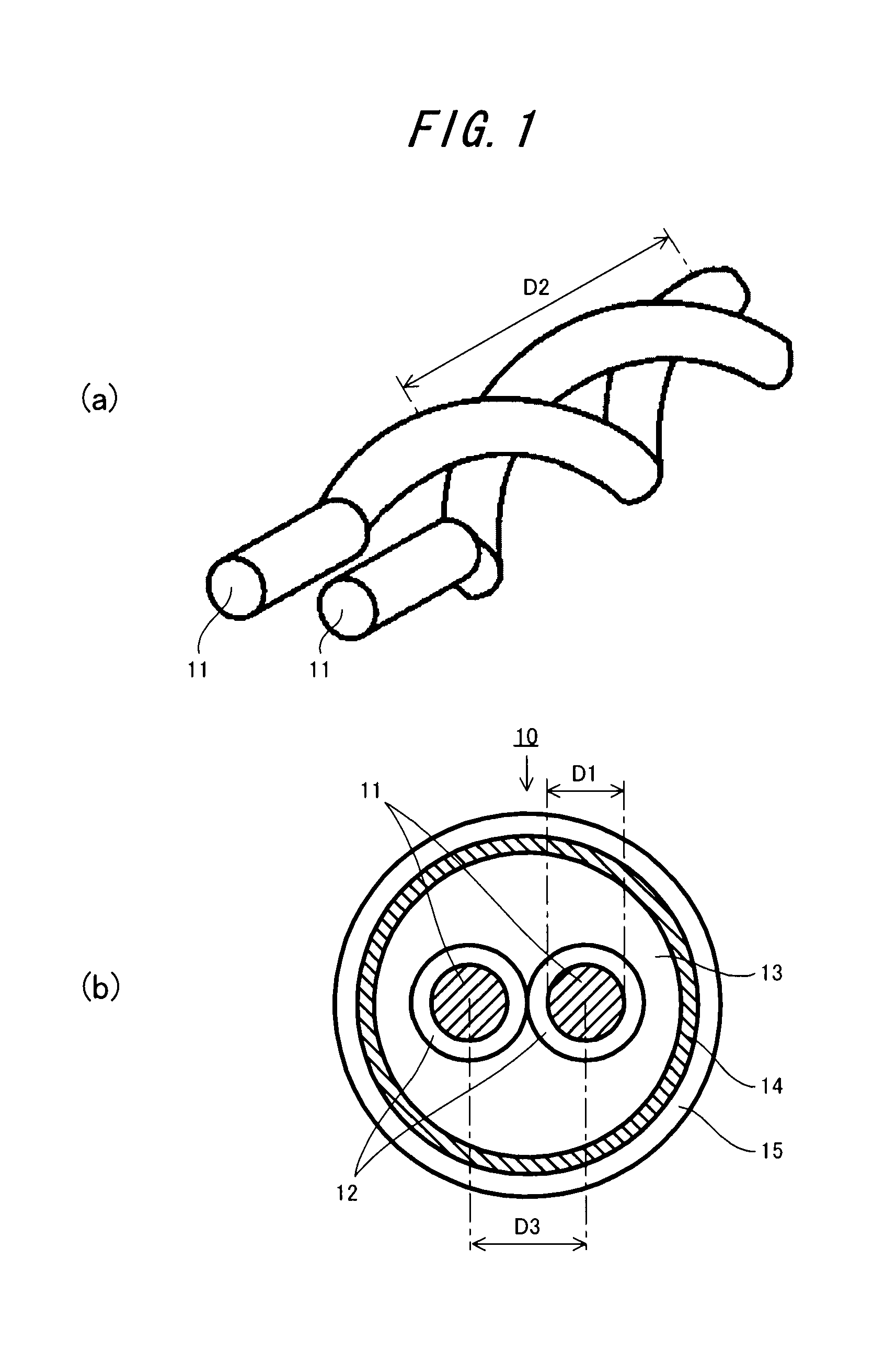
[0026]A wire (twisted pair cable) 10 according to the embodiment of the present invention is explained with reference to FIG. 1.

[0027]As shown in FIGS. 1 (a) and (b), the twisted pair cable 10 according to the present embodiment is configured with a core wire 11, a first coating material 12, a second coating material 13, a shield material 14, and an exterior material 15. The twisted pair cable 10 is formed so that the characteristic impedance becomes about 135 Ωor more, and preferably 200 Ω.

[0028]The core wire 11 is constituted with an electrically conductive material such as copper, and it is formed in a twisted shape by twisting two wires. The diameter D1 of the core wire 11 is about 0.2 mm to 0.4 mm, and preferably 0.3 mm. The pitch D2 of the core wire 11 is about 9 mm to 11 mm, and preferably 10.3 mm. The spacing D3 of two core wires 11 is about 1.2 mm to 1.4 mm, and preferably 1.36 mm. Moreover, in the case that the length of the twisted pair cable 10 is on the order of 100 m, ...


PUM

PropertyMeasurementUnit
impedanceaaaaaaaaaa
impedanceaaaaaaaaaa
impedanceaaaaaaaaaa

Abstract

A wire (a twisted pair cable) that transmits a gigahertz band signal and that is provided with a pair of core wires that are twisted with each other, a first insulation coating material, a second insulation coating material, and a shield material that shields evanescent waves emitted from the pair of core wires. The pair of core wires have a twisting pitch, a diameter, and a spacing so that the wire has a characteristic impedance of 100 to 200Ω and the phases of the TEM (Transverse Electro-Magnetic) wave and the evanescent wave that are emitted from the pair of core wires are matched.

Description

TECHNICAL FIELD[0001]The present invention relates to a wire that is preferable for transmitting a gigahertz band high frequency signal, and a composite wire.BACKGROUND ART[0002]Recently, a coaxial line, a twisted pair line and the like have become known as a transmission line of a TEM (Transverse Electro-Magnetic) wave. However, because DC resistance (R0) and dielectric loss (G0) exist in the transmission line, the signal attenuates during transmission. Especially in the case of transmitting a gigahertz band high frequency signal, because the characteristic impedance (Z0) in which the DC resistance (R0) and the dielectric loss (G0) are combined has a frequency characteristic, the signal attenuates greatly. Furthermore, when an electromagnetic wave transmission state is examined carefully in the transmission line of the high frequency signal, sidelobe-like electromagnetic emission is seen as an evanescent wave. Therefore, attenuation of the signal due to this evanescent wave becomes...

Claims


Application Information

Patent Timeline
Patent Type & Authority Applications(United States)
IPC IPC(8): H01B11/02
CPCH01P3/00
Inventor OTSUKA, KANJIUSAMI, TAMOTSUUEDA, CHIHIROAKIYAMA, YUTAKA
Owner IBIDEN CO LTD
Why Eureka
Try Eureka