
Remote controller, remote control system and program

a remote control system and remote control technology, applied in the direction of electric programme control, program control, instruments, etc., can solve the problems of user difficulty in confirming the arrangement of the operation elements by touch, user may not be able to continue the desired operation, and erroneous operation may occur without an operation of the desired operation elemen

Active Publication Date: 2011-02-24
SONY CORP
View PDF5 Cites 12 Cited by
  • Summary
  • Abstract
  • Description
  • Claims
  • Application Information

AI Technical Summary

Problems solved by technology

In this case, even when the user has once confirmed the arrangement of the operation elements, the user is difficult to confirm the arrangement of the operation elements by the sense of touch as well as to correct the position of the finger if necessary.
Accordingly, if the position of the finger is involuntarily moved through a continuous operation, an erroneous operation may occur without an operation of a desired operation element.
Thus, the user may not be able to continue the desired operation while paying attention to the external device to some extent.

Method used


Image

  • Remote controller, remote control system and program
  • Remote controller, remote control system and program
  • Remote controller, remote control system and program

Examples


first embodiment

[0050][3. First Embodiment]

[0051]In the following, a remote control method consistent with a first embodiment of the present invention will be described with reference to FIG. 4 and FIGS. 5A to 5D. FIG. 4 and FIGS. 5A to 5D are a flow diagram and explanatory diagrams showing the remote control method consistent with the first embodiment of the present invention.

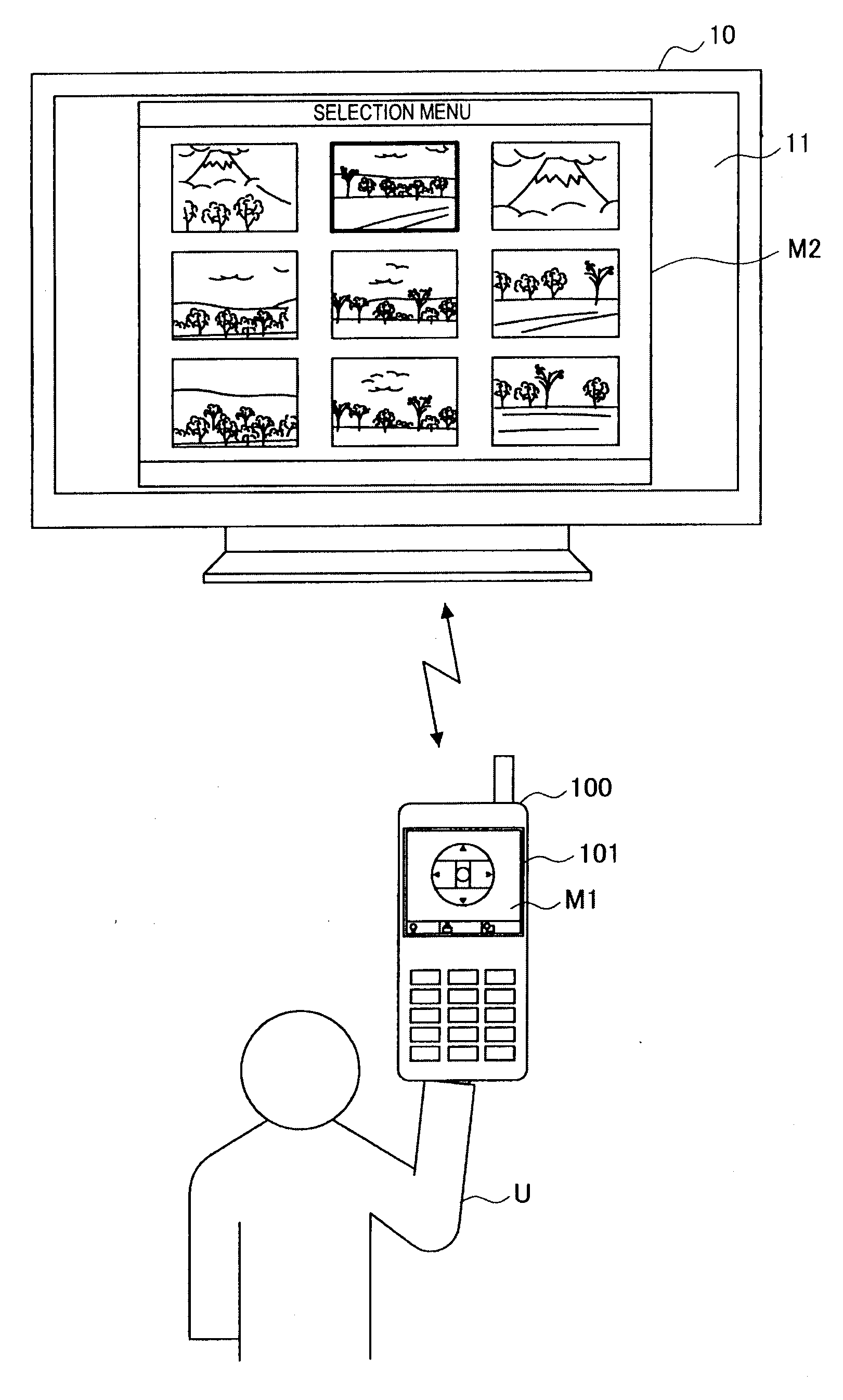
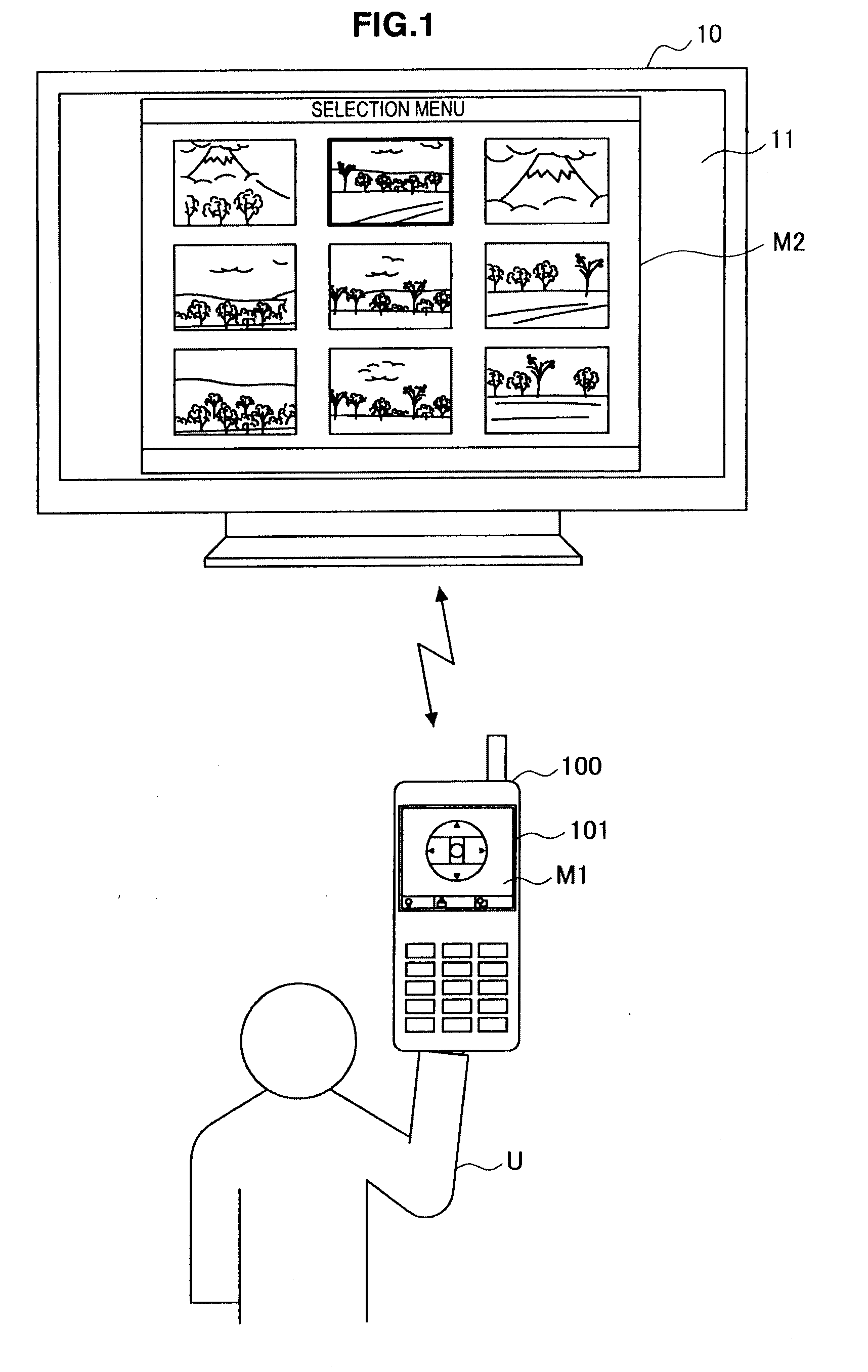
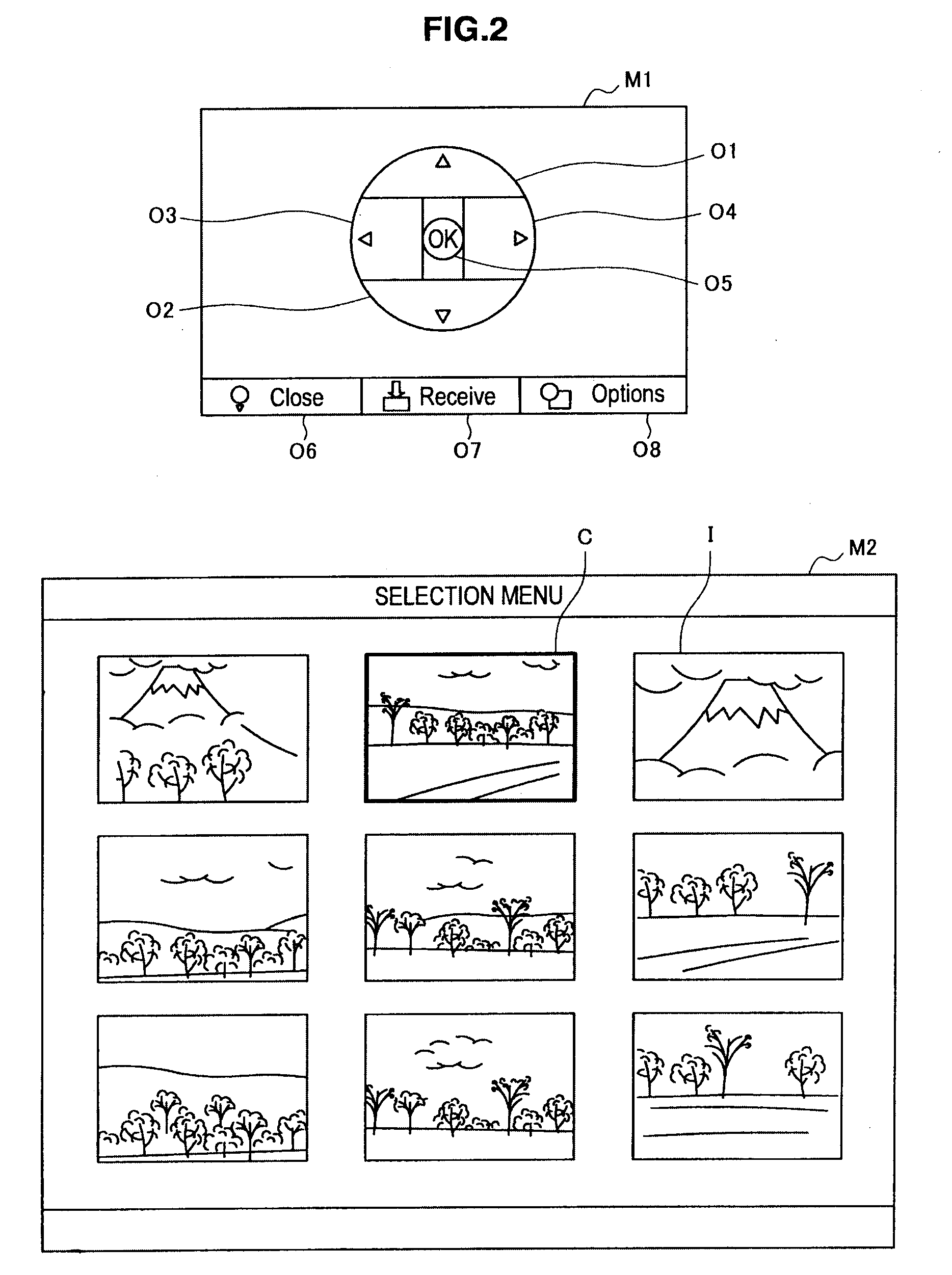
[0052]The detection area setting unit 105 sets (initialize) a predetermined detection area A for each object O based on the object data (step S101). Here, as shown in FIG. 5A, each of the predetermined detection areas A (A1 to A5) is exclusively set so as to include the display area of each of the objects O (buttons O1 to O5). In addition, the detection area A is not limited to a rectangular shape and may be set to an arbitrary shape.

[0053]The contact detection unit 103 determines whether contact of the pointer is detected within the detection area A of an arbitrary object O (S103). When the contact is detected, the object O ...

second embodiment

[0073][4. Second Embodiment]

[0074]In the following, a remote control method consistent with a second embodiment of the present invention will be described with reference to FIG. 7 and FIGS. 8A to 8E. FIG. 7 and FIGS. 8A to 8E are a flow diagram and explanatory diagrams showing the remote control method consistent with the second embodiment of the present invention. In addition, in FIG. 7, the processing in the steps preceding the step S105 and the processing in the steps following the step S109 are omitted. In the second embodiment, change processing of the operation target object Ot is added in between the processing in the step S105 and the processing in the step S109 of the first embodiment.

[0075]When an operation target object Ot is set in the processing of the step S105, the remote control unit 107 notifies the television 10 of the setting status of the operation target object Ot and a display instruction (S201). When having received the display instruction, the television 10 d...


PUM


Abstract

A user interface apparatus, a method for controlling a user interface apparatus, and a computer-readable medium are provided. The user interface apparatus includes a display unit comprising an object display area, the display unit displaying an object in the object display area; a detection area control unit that (1) defines a detection area for the object, the detection area including the object display area and having a size and a location, and (2) changes at least one of the size and the location of the detection area to create a modified detection area; and an activation detection unit that detects a position of a user activation. Furthermore, the detection area control unit changes the detection area after the activation detection unit detects the activation position as being within the detection area.

Description

BACKGROUND[0001]1. Technical Field[0002]The present invention relates to a remote controller, a remote control system and a program.[0003]2. Description of the Related Art[0004]There has been known a remote controller such as a remote controller for remote controlling an external device such as a television receiver. Generally, the status of the external device changes in response to an operation of the remote controller, so that a user can confirm the execution of the operation through the change in the status of the external device. Thus, once the user has confirmed an arrangement of operation elements on the remote controller, the user tends to continue a desired operation in a state of paying attention to the external device without looking at the remote controller.[0005]Here, in the case of operating operation elements provided to the remote controller in the form of hardware, the user can confirm the arrangement of the operation elements to some extent by the sense of touch an...

Claims


Application Information

Patent Timeline
Patent Type & Authority Applications(United States)
IPC IPC(8): G05B19/02G06F3/048G06F3/0488
CPCH04N5/4403H04N2005/4425H04N2005/443H04N21/42224H04N21/42209H04N21/4222H04N21/42204
Inventor OHKI, YOSHIHITO
Owner SONY CORP
Learn More