Projector
a projector and projector technology, applied in the field of projectors, can solve the problems of difficult to further brighten the projection image, difficult to stabilize the color balance of the projection image, and significant thermal load concentrated on the single solid-state light source device, so as to achieve the effect of suppressing the degradation of color reproducibility or deterioration of the light modulation devi
- Summary
- Abstract
- Description
- Claims
- Application Information
AI Technical Summary
Benefits of technology
Problems solved by technology
Method used
Image

Examples
first embodiment
[0052]First, the configuration of a projector 1000 according to a first embodiment will be described.
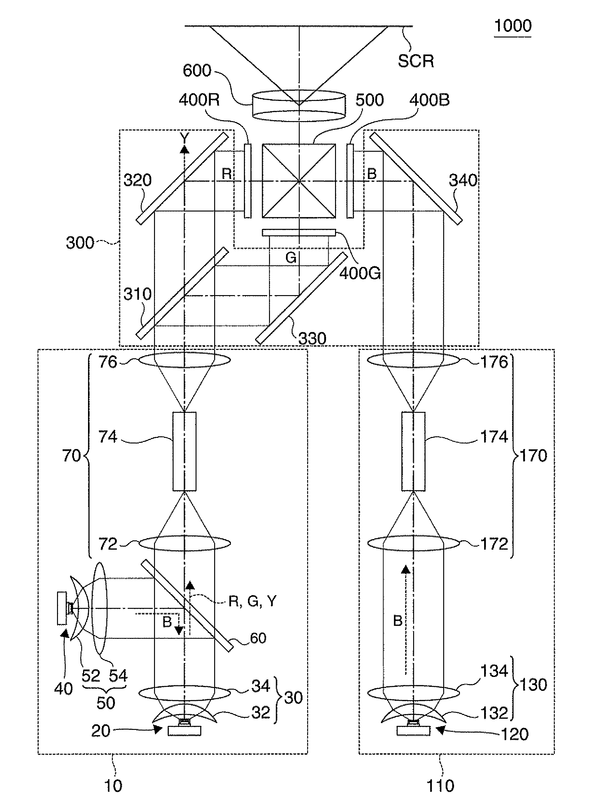
[0053]FIG. 1 is a plan view showing optical systems of a projector 1000 according to a first embodiment.
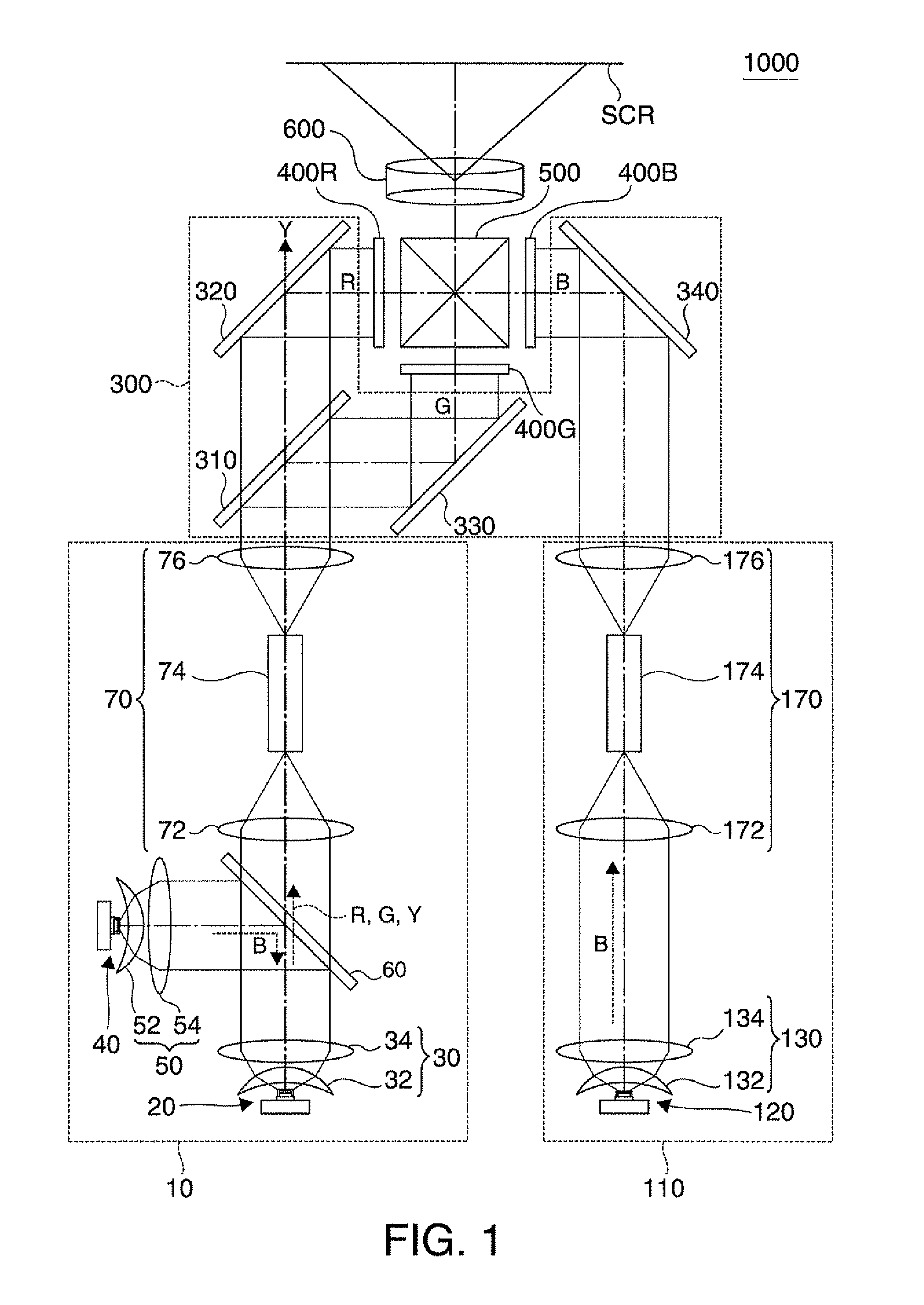
[0054]FIGS. 2A to 2C are diagrams illustrating a first solid-state light source device 20, a third solid-state light source device 40, and a second solid-state light source device 120 in the projector 1000 according to the first embodiment. FIG. 2A is a sectional view of a first solid-state light source device 20. FIG. 2B is a sectional view of a third solid-state light source device 40. FIG. 2C is a sectional view of a second solid-state light source device 120.
[0055]FIGS. 3A to 3D are graphs showing relative light-emission intensity of a first solid-state light source 24, a fluorescent layer 28, a third solid-state light source 44, and a second solid-state light source 124 in the projector 1000 according to the first embodiment. FIG. 3A is a graph showing relative light-emission ...
second embodiment
[0110]FIG. 4 is a plan view showing optical systems of a projector 1002 according to a second embodiment.
[0111]The projector 1002 of the second embodiment basically has the same configuration as the projector 1000 of the first embodiment, but a first illumination device has the configuration different from that in the projector 1000 of the first embodiment.
[0112]That is, in the projector 1002 of the second embodiment, as shown in FIG. 4, a first illumination device 12 further includes a reflection-type polarizing plate 80 which is located at the back of the collimation optical system 30 to directly transmit one polarized component (for example, s polarized component) from among polarized components included in light emitted from the first solid-state light source device 20 and to reflect another polarized component (for example, p polarized component) toward the fluorescent layer 26. The reflection-type polarizing plate 80 is a wire grid polarizing plate which has fine metal wires d...
third embodiment
[0117]FIG. 5 is a plan view showing optical systems of a projector 1004 according to a third embodiment.
[0118]The projector 1004 of the third embodiment basically has the same configuration as the projector 1000 of the first embodiment, but a light modulation device and a color separating and guiding optical system have the configuration different from those in the projector 1000 of the first embodiment.
[0119]That is, in the projector 1004 of the third embodiment, as shown in FIG. 5, a light modulation device has reflection-type liquid crystal light modulation devices 402R, 402G, and 402B. A color separating and guiding optical system is a color separating and guiding optical system 304. The color separating and guiding optical system 304 has a dichroic mirror 310 which reflects a green light component and transmits other color light components, and reflection-type polarizing plates 322, 332, and 342 which directly transmit one polarized component (for example, s polarized component...
PUM
 Abstract
Description
Claims
Application Information
 - R&D
- Intellectual Property
- Life Sciences
- Materials
- Tech Scout
- Unparalleled Data Quality
- Higher Quality Content
- 60% Fewer Hallucinations
Browse by: Latest US Patents, China's latest patents, Technical Efficacy Thesaurus, Application Domain, Technology Topic, Popular Technical Reports.
© 2025 PatSnap. All rights reserved.Legal|Privacy policy|Modern Slavery Act Transparency Statement|Sitemap|About US| Contact US: help@patsnap.com