Projector

a projector and projection image technology, applied in the field of projectors, can solve the problems of difficult to further brighten the projection image, difficult to stabilize the color balance of the projection image, and concentrated thermal load on the single solid-state light source device, so as to improve the efficiency of light us

Active Publication Date: 2011-02-24
SEIKO EPSON CORP
View PDF26 Cites 25 Cited by
  • Summary
  • Abstract
  • Description
  • Claims
  • Application Information

AI Technical Summary

Benefits of technology

[0045]However, with the above-described configuration, part of excitation light reflected by the excitation light reflection optical system is not absorbed by the reflection-type polarizing plate. Therefore, light use efficiency can be improved.

Problems solved by technology

However, according to the projector described in JP-A-2005-274957, since white light including a red light component, a green light component, and a blue light component is generated from the single solid-state light source device, unlike a projector which includes three solid-state light source devices, a significant thermal load is concentrated on the single solid-state light source device.
As a result, it is difficult to further brighten the projection image.
For this reason, it is difficult to stabilize the color balance of the projection image.
Meanwhile, there is a problem in that a solid-state light source which is used in a solid-state light source device emitting a green light component has relatively low light-emission efficiency compared to a solid-state light source which is used in a solid-state light source device emitting a red light component and a solid-state light source which is used in a solid-state light source device emitting a blue light component.
Meanwhile, in the projector according to the aspect of the invention, part of excitation light emitted from the first solid-state light source device may transmit the fluorescent layer directly, which may cause degradation in light use efficiency, or deterioration in color reproducibility or deterioration of the light modulation device.
Thus, when a light source which emits light including one polarized component and another polarized component is used as the light source of the projector, it is necessary to remove another polarized component by an incidence-side polarizing plate, which causes degradation in light use efficiency.
Meanwhile, if the reflection-type polarizing plate is disposed in front of the excitation light reflection optical system, part of excitation light reflected by the excitation light reflection optical system may be absorbed by the reflection-type polarizing plate, such that it may be difficult to improve light use efficiency.

Method used


Image

  • Projector
  • Projector
  • Projector

Examples


first embodiment

[0056]First, the configuration of a projector 1000 according to a first embodiment will be described.

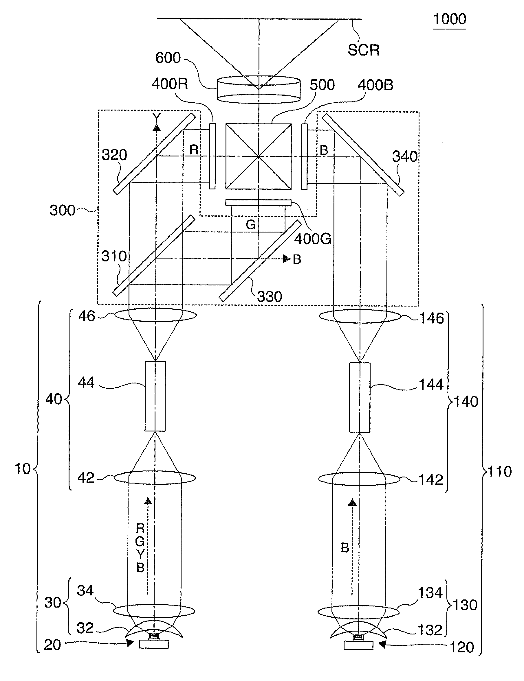
[0057]FIG. 1 is a plan view showing optical systems of the projector 1000 according to the first embodiment.

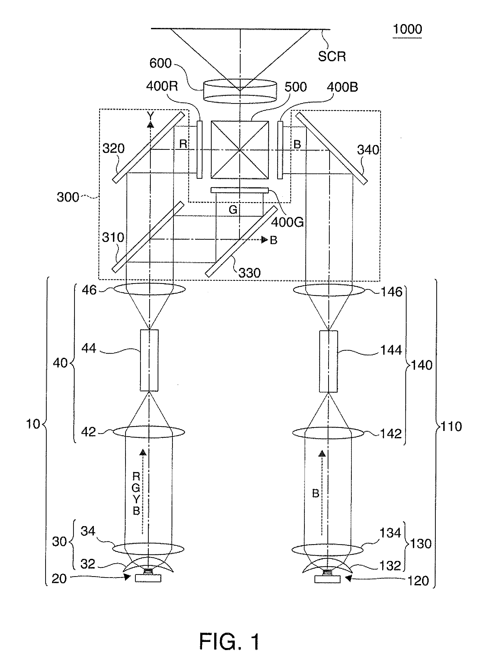
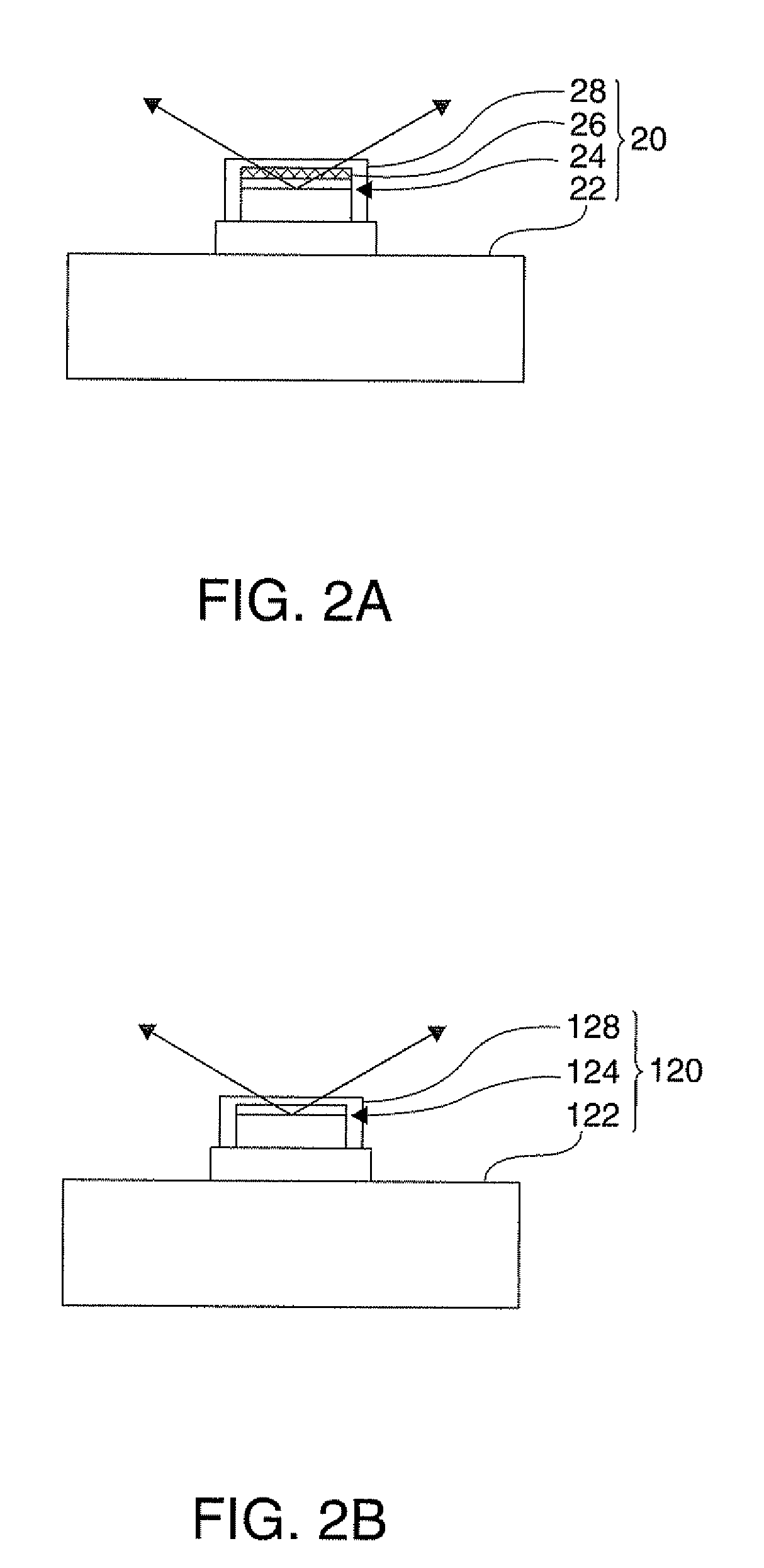
[0058]FIGS. 2A and 2B are diagrams illustrating a first solid-state light source device 20 and a second solid-state light source device 120 in the projector 1000 according to the first embodiment. FIG. 2A is a sectional view of the first solid-state light source device 20. FIG. 2B is a sectional view of the second solid-state light source device 120.

[0059]FIGS. 3A to 3C are graphs showing relative light-emission intensity of a first solid-state light source 24, a fluorescent layer 26, and a second solid-state light source 124 in the projector 1000 according to the first embodiment. FIG. 3A is a graph showing relative light-emission intensity of a first solid-state light source 24. FIG. 3B is a graph showing relative light-emission intensity of a fluorescent layer 26. FIG. 3C is...

second embodiment

[0105]FIG. 4 is a plan view showing optical systems of a projector 1002 according to a second embodiment.

[0106]The projector 1002 of the second embodiment basically has the same configuration as the projector 1000 of the first embodiment, but a first illumination device and a color separating and guiding optical system have the configuration different from those in the projector 1000 of the first embodiment.

[0107]That is, in the projector 1002 of the second embodiment, as shown in FIG. 4, a first illumination device 12 further includes an excitation light reflecting mirror 50, serving as an excitation light reflection optical system, which is located at the back of the collimation optical system 30, separates light emitted from the fluorescent layer 26 (red light component, green light component, and yellow light component) from excitation light (blue light component) emitted while being not converted by the fluorescent layer 26, and returns excitation light (blue light component), ...

third embodiment

[0113]FIG. 5 is a plan view showing optical systems of a projector 1004 according to a third embodiment.

[0114]The projector 1004 of the third embodiment basically has the same configuration as the projector 1002 of the second embodiment, but the configuration of the first illumination device is different from that in the projector 1002 of the second embodiment.

[0115]That is, in the projector 1004 of the third embodiment, as shown in FIG. 5, the first illumination device 14 further includes a reflection-type polarizing plate 52 which is located at the back of the collimation optical system 30, directly transmits one polarized component (for example, s polarized component) from among polarized components included in light emitted from the first solid-state light source device 20, and reflects another polarized component (for example, p polarized component) toward the fluorescent layer 26. The reflection-type polarizing plate 52 is a wire grid polarizing plate which has fine metal wire...


PUM


Abstract

A projector includes: a first solid-state light source device which includes a first solid-state light source emitting excitation light, and a fluorescent layer converting excitation light emitted from the first solid-state light source to light including a first color light component and a second color light component different from the first color light component, and emitting converted light; a second solid-state light source device which includes a second solid-state light source emitting a third color light component different from the first color light component and the second color light component; a light modulation device modulating the first color light component, the second color light component, and the third color light component in accordance with image information; and a projection optical system projecting the modulated light components from the light modulation device as a projection image.

Description

BACKGROUND[0001]1. Technical Field[0002]The present invention relates to a projector, and in particular, to a projector using a solid-state light source.[0003]2. Related Art[0004]A projector is known which includes a single solid-state light source device emitting white light, a color separating and guiding optical system separating light from the single solid-state light source device into a red light component, a green light component, and a blue light component, a light modulation device modulating the respective color light components from the color separating and guiding optical system in accordance with image information, and a projection optical system projecting the modulated light components from the light modulation device as a projection image (for example, see JP-A-2005-274957). According to the projector described in JP-A-2005-274957, the three color light components which are obtained by separating white light emitted from the single solid-state light source device are...

Claims


Application Information

Patent Timeline
Patent Type & Authority Applications(United States)
IPC IPC(8): G03B21/14G03B21/00F21V9/40
CPCG03B33/12H04N9/3155G03B21/204H04N9/3197G03B21/2013H04N9/3182
Inventor MIYAMAE, AKIRA
Owner SEIKO EPSON CORP
Why Eureka
Try Eureka