Docking station

a docking station and universal technology, applied in the direction of electrical apparatus construction details, instruments, casings/cabinets/drawers, etc., can solve the problems of sized and structured, hand held devices typically do not offer the most “user-friendly” input/output elements, etc., to achieve the effect of assisting in providing stability to electronic devices

Inactive Publication Date: 2011-02-24
BYRNE NORMAN R
View PDF32 Cites 19 Cited by
  • Summary
  • Abstract
  • Description
  • Claims
  • Application Information

AI Technical Summary

Benefits of technology

[0021]In accordance with other concepts, the device connector assembly and the main housing are structured so that when the electronic device is mechanically and electrically coupled to the docking station, the electronic device is prevented from tilting rearwardly to an extent that the mechanical and electrical coupling of the electronic device to the docking station would be disturbed. The device connector assembly includes a pivot assembly which is pivotally coupled to the docking station. In this manner, when the electronic device is mechanically and electrically coupled to the docking station, the pivot assembly will pivot in correspondence with any pivoting motion of the electronic device.
[0022]The docking station can include a base door which is coupled to the main housing. The pivot assembly can be directly and pivotally coupled to the base door. The base door can be rotatably coupled to the main housing. The device connector assembly is structured so that when the electronic device is mechanically and electrically coupled to the docking station, the device is initially tilted rearwardly toward the main housing. This tilting assists in providing stability to the electronic device.

Problems solved by technology

However, hand held devices typically do not offer the most “user-friendly” input / output elements, such as keyboards and a mouse typically found with personal computers.
One problem associated with a number of known docking stations is that they are sized and structured to accommodate only one type and size of hand held device.
One of the problems associated with known docking stations for accommodating hand held devices of differing sizes and shapes relates to stability.

Method used


Image

  • Docking station
  • Docking station
  • Docking station

Examples


Embodiment Construction

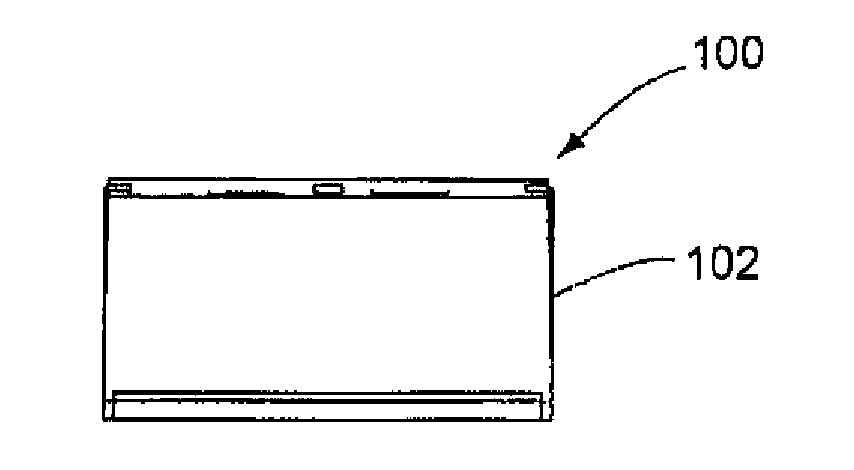
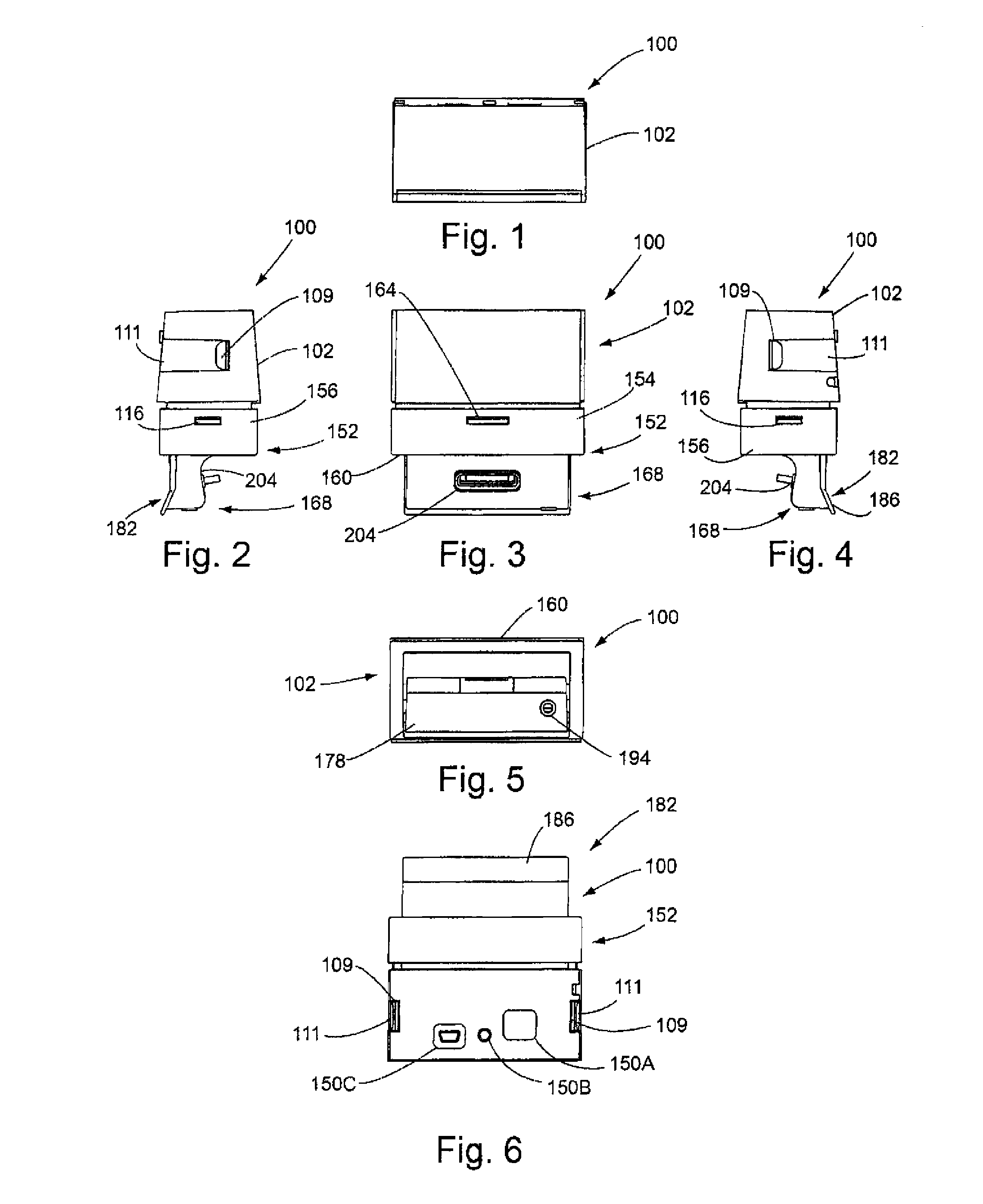
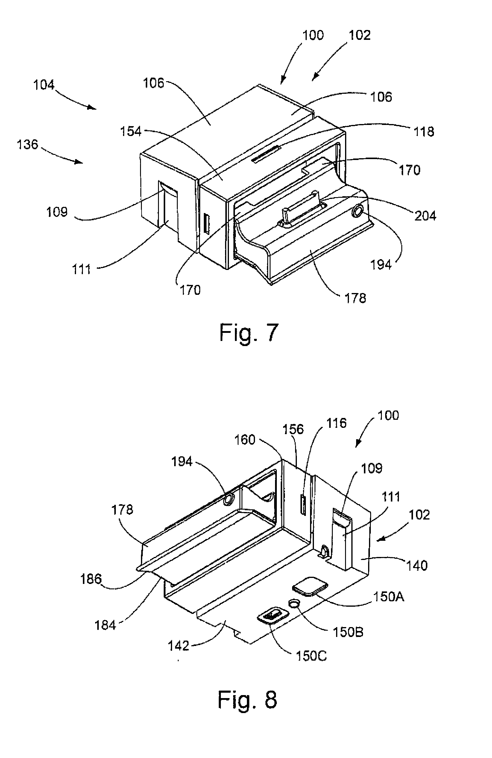
[0059]The principles of the invention are disclosed, by way of example, with respect to a docking station 100 as illustrated in FIGS. 1-31. The docking station 100, and other embodiments in accordance with the invention, efficiently provide for transfer of electrical signals between the docking station 100 and a hand held device, where the electrical signals may be in the form of charging power signals being transmitted to the hand held device or, alternatively, data communication signals or program communication signals between the station 100 and the device. In particular, docking stations in accordance with the invention accommodate hand held devices of differing thicknesses, while still maintaining the devices in stable positions relative to the docking station 100. Further, the configuration of the docking station 100 in accordance with the invention prevents interconnected hand held devices from inappropriately tilting in a manner such that the electrical and mechanical connec...


PUM


Abstract

A docking station (100) is adapted for charging or otherwise transmitting electrical signals to an electronic device (240). The docking station (100) includes a main housing (102) and a device connector assembly (204). The device connector assembly (204) is coupled to the main housing (102) and electronically connected to circuit components (130, 132) for mechanically and electrically coupling the electronic device (240) to the docking station (100).

Description

CROSS-REFERENCE TO RELATED APPLICATIONS[0001]This application claims priority of U.S. Provisional Application Ser. No. 61 / 049, 979 filed May 2, 2008.STATEMENT REGARDING FEDERALLY SPONSORED RESEARCH OR DEVELOPMENT[0002]Not applicable.PARTIES TO A JOINT RESEARCH AGREEMENT[0003]Not applicable.REFERENCE TO A SEQUENCE LISTING[0004]Not applicable.BACKGROUND OF THE INVENTION[0005]1. Field of the Invention[0006]The invention relates to apparatus for charging or otherwise transmitting electrical signals to or from a device to be removably connected to the apparatus and, more particularly, to a universal docking station for charging or otherwise transmitting electrical signals to or from a device such as a hand held electronic device.[0007]2. Background Art[0008]In today's electronic world, numerous types of portable electronic devices are now used for both commercial and personal purposes. These devices include such items as cell phones, personal data assistants (commonly referred to as “PDA...

Claims


Application Information

Patent Timeline
Patent Type & Authority Applications(United States)
IPC IPC(8): H05K7/00
CPCH01R35/02H01R2201/06G06F1/1632H04M1/04H02J7/0044
Inventor BYRNE, NORMAN R.
Owner BYRNE NORMAN R
Why Eureka
Try Eureka