Bullet or Projectile With Spiral Grooves

Inactive Publication Date: 2015-12-10
SCHNABEL ROBERT PETER
View PDF4 Cites 9 Cited by
  • Summary
  • Abstract
  • Description
  • Claims
  • Application Information

AI Technical Summary

Benefits of technology

[0005]The present invention is a unique bullet or projectile design in which the spiral grooves on the bullet can help increase bullet stability and velocity. This is important due to the ability of a equal amount of gunpowder to prov

Problems solved by technology

The conventional bullet design with a smooth surface also has limited ballistics based on current smooth surface

Method used


Image

  • Bullet or Projectile With Spiral Grooves
  • Bullet or Projectile With Spiral Grooves
  • Bullet or Projectile With Spiral Grooves

Examples


Embodiment Construction

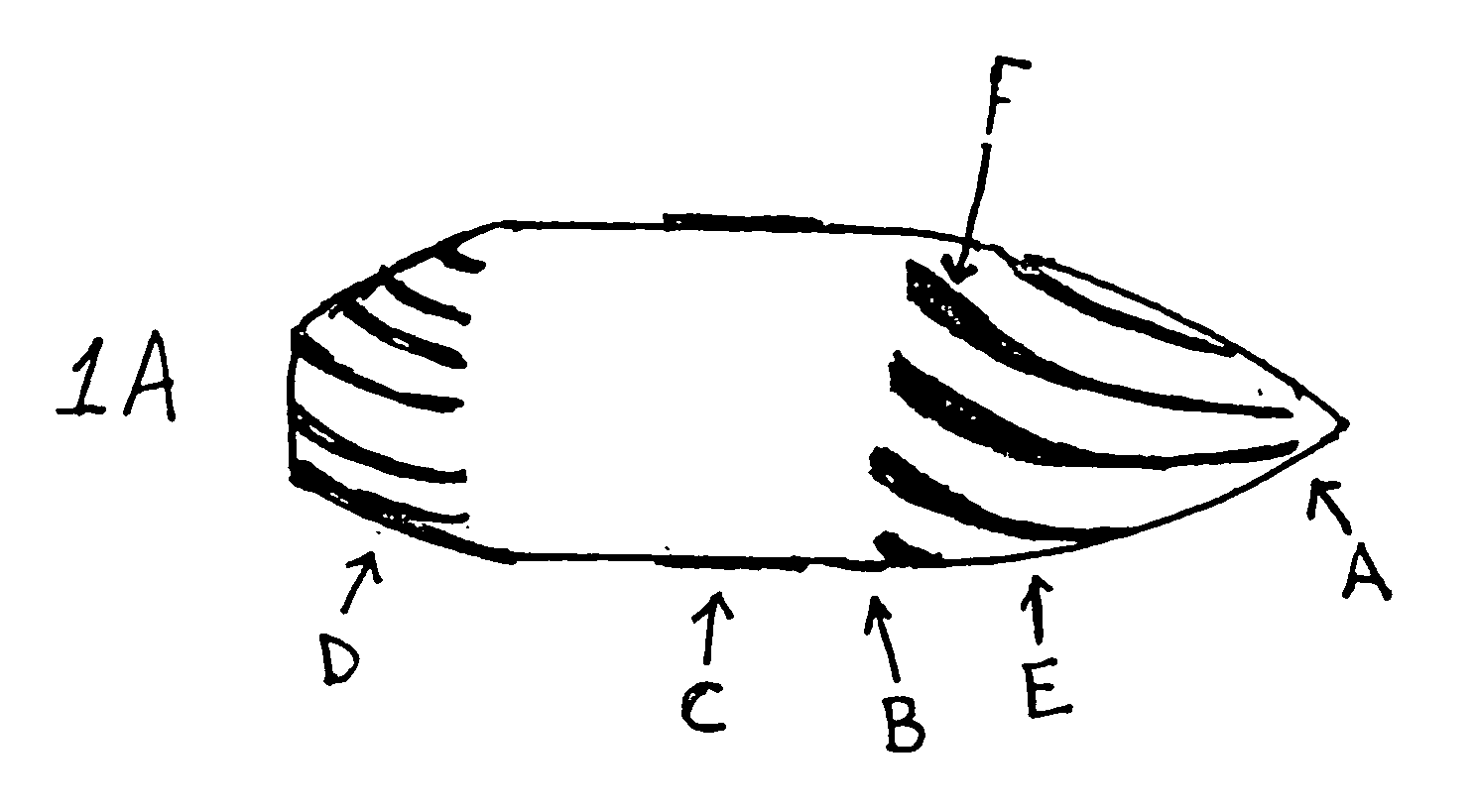
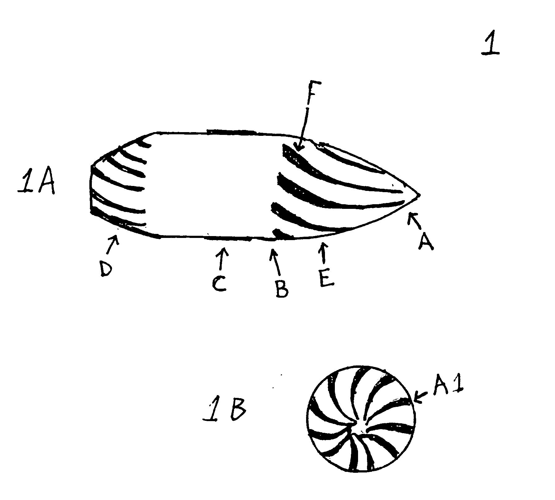
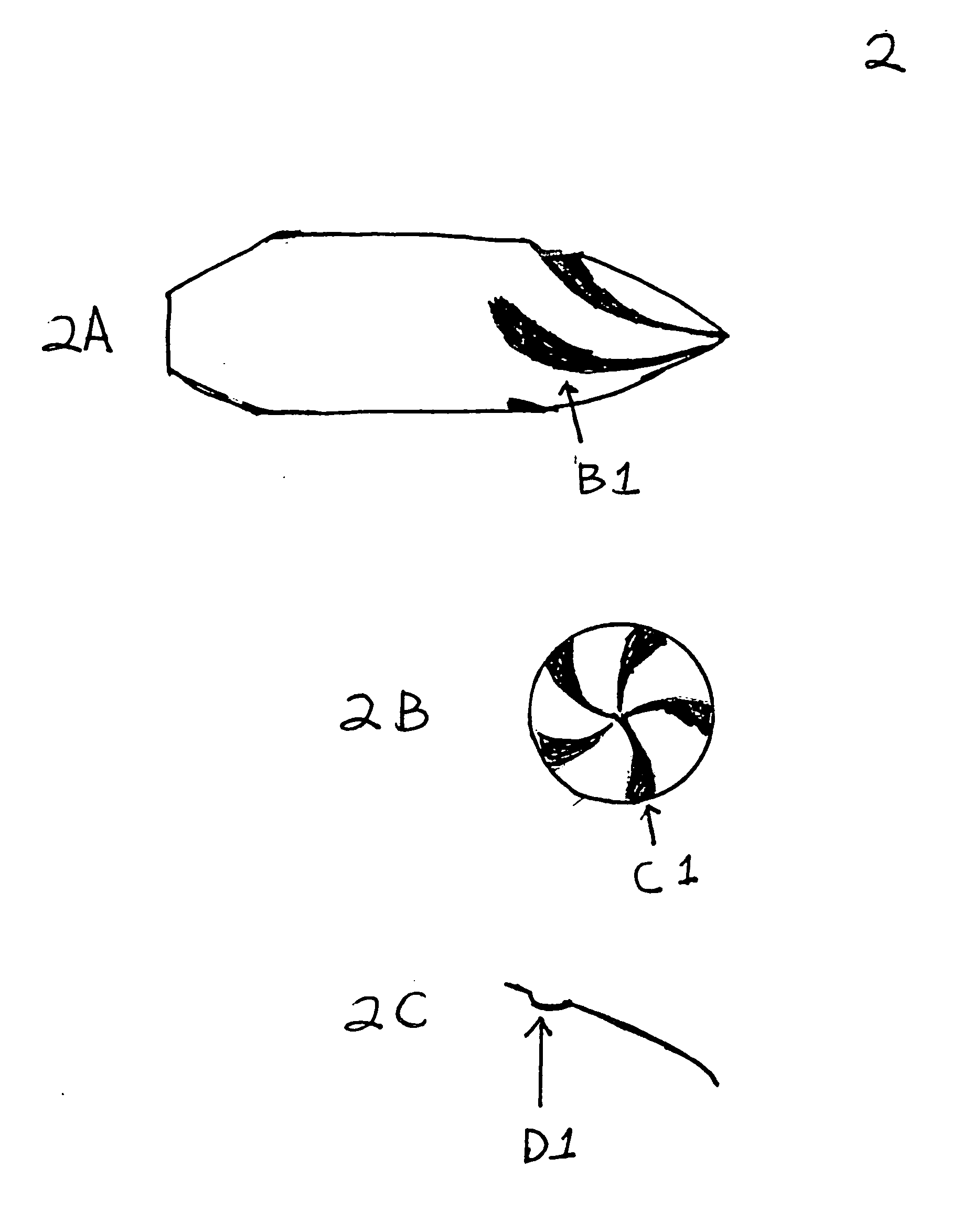
[0015]A bullet is generally designed with a nose A, ogive E, bore rider B, driving band C and boat tail D, but some designs may not include all of the features or may include additional features. The groove depth, width, and angle can vary depending on the bullet caliber, load, and desired performance. The groove depth and width may also very along the surface of the bullet. For example, the start of the ogive at the nose may have a very minimal groove depth, but as the spiral groove moves along the ogive the groove could get deeper, wider and the angle of the groove could change.

[0016]The grooves could be machined efficiently in an existing bullet with a CNC milling machine or a CNC lathe while utilizing the appropriate tooling to cut the groove. The bullets could also be cast in a mold which contains the grooves, so upon ejection from the mold the bullet is a finished product. The grooves could also be imparted during the forming process of a FMJ bullet or in a injection molding p...


PUM


Abstract

A bullet or projectile having surface geometry in the form of a spiral or partial spiral groove. The spiral can be formed, cast or machined and very in depth, angle, and width. The spiral may go from the nose to the end of the bullet in one continual grove or the spiral may be focused on certain, areas of the bullet. The bullet may consist of any material capable of being formed, cast or machined and be of any caliber.

Description

CROSS-REFERENCE TO RELATED APPLICATIONS[0001]Not ApplicableSTATEMENT REGARDING FEDERALLY SPONSORED RESEARCH OR DEVELOPMENT[0002]Not ApplicableREFERENCE TO SEQUENCE LISTING, A TABLE OR A COMPUTER PROGRAM LISTING COMPACT DISC APPENDIX[0003]Not ApplicableBACKGROUND OF THE INVENTION[0004]The present invention relates to bullets or projectiles, more specifically bullets with spiral or partial spiral grooves on the surface of the bullet. Conventional bullet designs consist of a basically smooth surface. The smooth surface relies on the rifling in the firearm barrel to impart spin on the bullet to obtain its gyroscopic stability. The conventional bullet design with a smooth surface also has limited ballistics based on current smooth surface with no spiral grooves on the surface of the bullet other than what is imparted from the rifling in the barrel.BRIEF SUMMARY OF THE INVENTION[0005]The present invention is a unique bullet or projectile design in which the spiral grooves on the bullet ca...

Claims


Application Information

Patent Timeline
IPC IPC(8): F42B30/02
CPCF42B30/02F42B10/24
Inventor SCHNABEL, ROBERT PETER
Owner SCHNABEL ROBERT PETER
Why Eureka
Try Eureka