Suspended abrasive waterjet hole drilling system and method

a waterjet hole and abrasive technology, applied in the field of hole drilling, can solve the problems of not meeting the special concerns of hole drilling, recast material on the side of the hole wall that is prone to cracking and failure, and is not suitable for drilling small diameter holes, etc., to achieve high abrasive particle velocities, increase fluid viscosity, and increase fluid viscosity

Active Publication Date: 2007-03-06
RTX CORP
View PDF5 Cites 58 Cited by
  • Summary
  • Abstract
  • Description
  • Claims
  • Application Information

AI Technical Summary

Benefits of technology

[0006]The present invention is directed to a hole drilling system and method that uses coherent abrasive suspension jets to drill holes in a target. Abrasive particles are suspended in a working fluid before the fluid is jetted toward the target by increasing the fluid viscosity before the abrasive material is added to the fluid. To achieve mixing of the water and abrasive prior to the forming of the jet, suitable polymeric materials are mixed with the working fluid water to achieve an increased fluid viscosity, ensuring that the jet that is outputted through the system is coherent rather than divergent to maintain high abrasive particle velocities to drill holes efficiently. Further, by keeping the jet coherent at high velocities, the invention can cleanly drill holes even if the desired holes have small diameters without creating any thermal damage in the hole.
[0007]One advantage of the process for hole drilling with a coherent abrasive suspension jet is the elimination of the dry abrasive mixing chamber and focusing tube used in conventional abrasive waterjet hole drilling systems. The coherent abrasive suspension jet utilizes a viscous or viscoelastic suspension that maintains the abrasive in an even distribution throughout the liquid so that it might easily be pumped and passed through the nozzle already mixed. This permits the use of very small and closely spaced orifices to simultaneously drill multiple holes, including shallow-angled holes in confined, non line-of-sight locations.
[0008]In one embodiment, the jet nozzles used in the inventive system are smaller and narrower than conventional abrasive jet nozzles because the pre-mixed abrasive and fluid does not require two separate conduits, one for the abrasive and one for the fluid, to conduct mixing within a chamber disposed just before the nozzle. As a result, multiple nozzles can be arranged closely together to drill multiple, closely-spaced holes simultaneously.

Problems solved by technology

Mechanical drilling systems are appropriate for forming relatively large holes, but are not suitable for drilling small diameter holes because mechanical drilling methods are unable to drill small holes cleanly within tight tolerances.
However, these processes are thermal processes and often cause metallurgical damage in the holes they drill, leaving recast material on the sides of the hole walls that are prone to cracking and failure if highly stressed.
However, the '434 patent focuses solely using the jet in a cutting process and does not address the special concerns of hole drilling in any way.
The large physical dimensions of conventional waterjet system components severely limits the ability to drill holes in confined spaces and / or in closely-spaced hole patterns.

Method used


Image

  • Suspended abrasive waterjet hole drilling system and method
  • Suspended abrasive waterjet hole drilling system and method
  • Suspended abrasive waterjet hole drilling system and method

Examples


Embodiment Construction

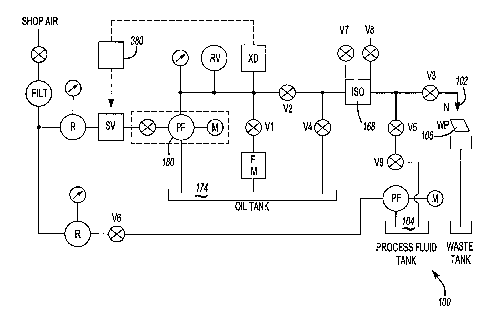
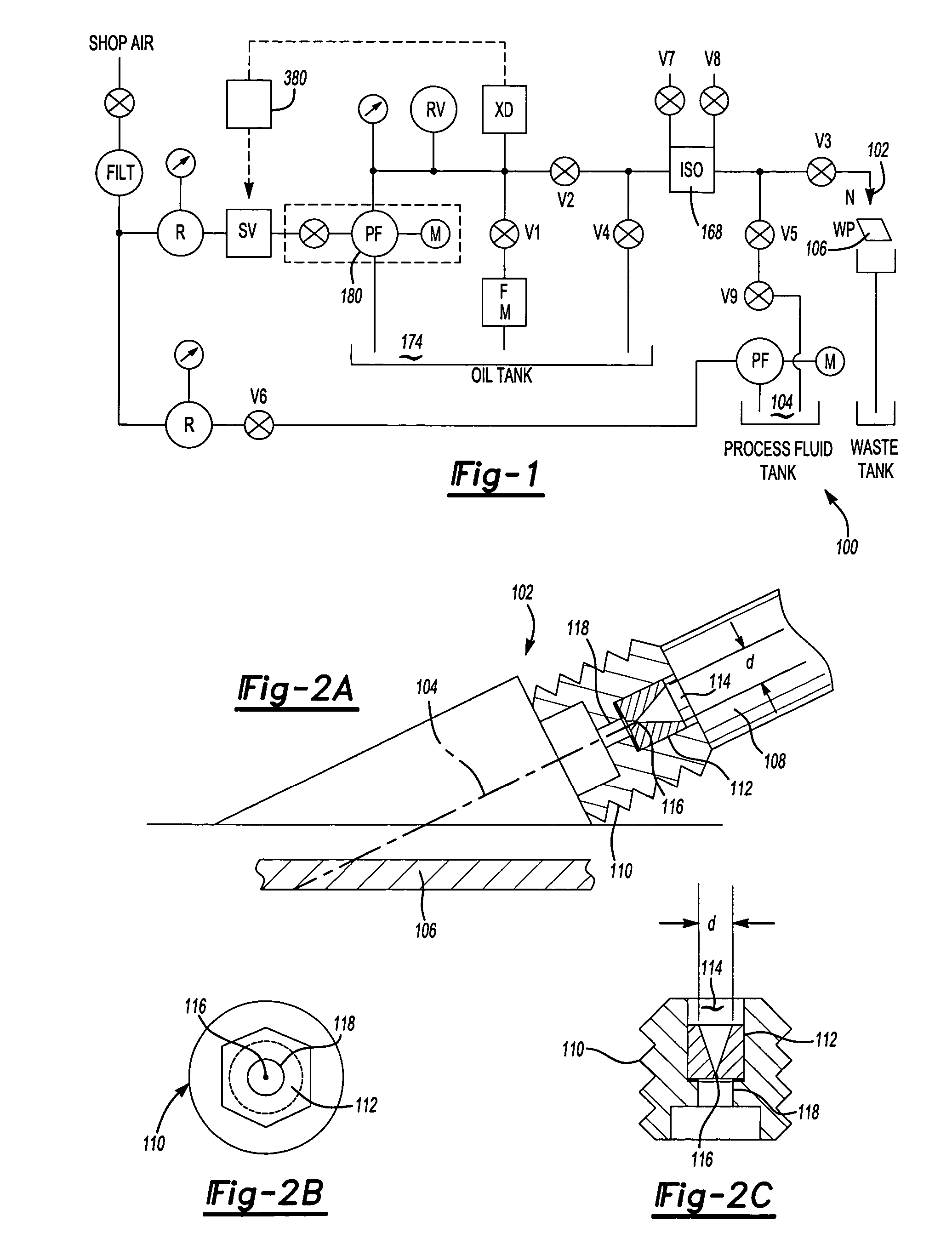
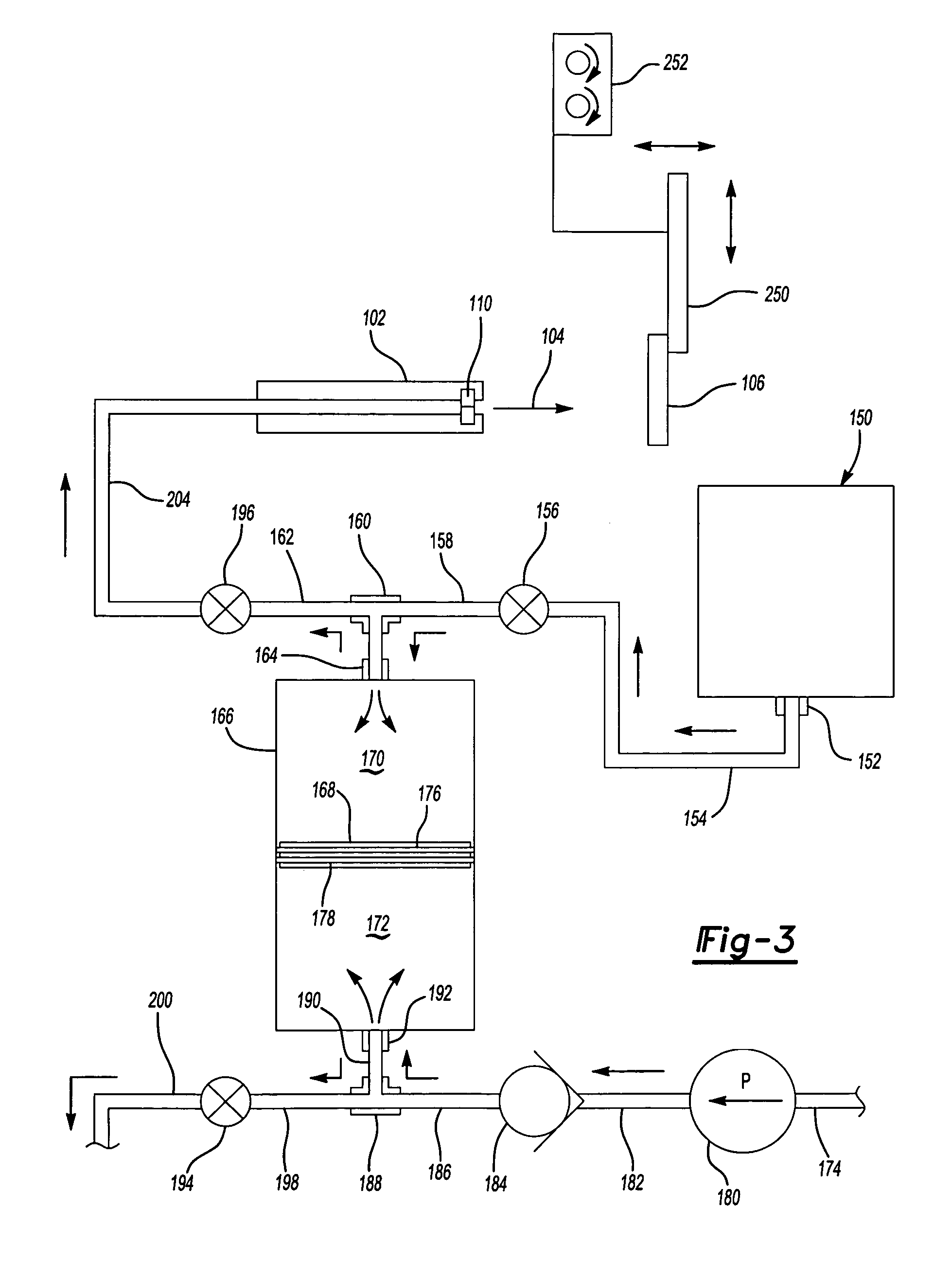
[0014]FIG. 1 is a schematic diagram illustrating various primary components of a drilling system 100 according to one embodiment of the invention. Generally, the system 100 sends an abrasive working fluid 104 through one or more jet heads 102 to a target 106. The flow and pressure of the working fluid 104 is controlled by flow of a control fluid 174, such as oil, hydraulic fluid, or water, through the system 100 via a series of valves. In the schematic shown in FIG. 1, an isolator 168 prevents the working fluid 104 from contacting the control fluid 174. An air-driven intensifier pump 180 is used to control the pressure of the control fluid 174 and therefore the working fluid 104. In one embodiment, the intensifier pump 180 is able to produce 10,000 psi of control fluid 174 at up to 6 gallons / minute with no compressible or inertial stored energy via control of a high-speed pneumatic servo valve SV.

[0015]The isolator 168 is charged by manipulation of various valves in the system 100. ...


PUM

PropertyMeasurementUnit
diameteraaaaaaaaaa
pressureaaaaaaaaaa
diameteraaaaaaaaaa

Abstract

A suspended abrasive waterjet narrow kerf cutting method is reconfigured to simultaneously drill multiple, closely-spaced holes in a target, including holes in confined non line-of-sight locations. Working fluid nozzles can be located on a flat or non-flat tool surface and arranged in uniform or non-uniform patterns, in an angled or perpendicular orientation, and in parallel or non-parallel arrangements. Individual nozzles or nozzle groups can be easily changed to provide increased or diminished working diameters, allowing control over the hole sizes and resultant airflow thru the drilled workpiece.

Description

TECHNICAL FIELD[0001]The present invention is directed to hole drilling, and more particularly to a hole drilling system and method that uses high pressure liquid to drill holes in a part.BACKGROUND OF THE INVENTION[0002]Many manufacturing applications require hole drilling to form holes in a target product. Mechanical drilling systems are appropriate for forming relatively large holes, but are not suitable for drilling small diameter holes because mechanical drilling methods are unable to drill small holes cleanly within tight tolerances.[0003]Laser systems have been used in hole drilling systems because they can be precisely focused and can drill even small diameter holes relatively cleanly. However, these processes are thermal processes and often cause metallurgical damage in the holes they drill, leaving recast material on the sides of the hole walls that are prone to cracking and failure if highly stressed.[0004]U.S. Pat. No. 5,184,434 to Hollinger et al. (“the '434 patent”) il...

Claims


Application Information

Patent Timeline
Patent Type & Authority Patents(United States)
IPC IPC(8): B24B1/00B24C1/00B24C1/04B24C3/02B24C7/00E21B7/18
CPCB24C1/045B24C11/005B24C7/0007B24C3/02
Inventor JOSLIN, FREDERICK R.
Owner RTX CORP
Why Eureka
Try Eureka