Fuel supply system for fuel cell system designed to ensure stability in regulating flow rate of recirculated off-gas

a fuel supply system and off-gas technology, applied in the direction of fuel cells, cell components, solid electrolyte fuel cells, etc., can solve the problems of failure of flow regulator operation, inability to control difficulty in controlling the flow rate of off-gas to be recirculated to the fuel cell, etc., to achieve ease and increase the flow rate

Inactive Publication Date: 2005-07-07
DENSO CORP
View PDF10 Cites 52 Cited by
  • Summary
  • Abstract
  • Description
  • Claims
  • Application Information

AI Technical Summary

Benefits of technology

[0011] The above structure eliminates the need for an additional flow regulator in the off-gas recirculating line, thus avoiding the freeze problem experienced by the conventional structure, as discussed in the introductory part of this application. Use of the map, as illustrated in FIG. 3, which represents the pressure of the main supply fuel and the open area of the nozzle of the ejector device facilitates ease with which the flow rate of the off-gas to be recirculated is controlled as a function of a load on operation of the fuel cell.
[0012] In the preferred mode of the invention, when the voltage developed by the fuel cell drops below a given levels the controller controls the operations of the pressure regulator and the ejector device to incr

Problems solved by technology

Such pressure control of the fuel gas only by means of the regulation of the flow rate thereof, however, encounters a difficulty in controlling the flow rate of the off-gas to be recirculated to the fuel cell.
This system, however, encounters the drawback in that moisture created within the fuel cell flows into the off-gas recirculating line and may freeze, which results in

Method used


Image

  • Fuel supply system for fuel cell system designed to ensure stability in regulating flow rate of recirculated off-gas
  • Fuel supply system for fuel cell system designed to ensure stability in regulating flow rate of recirculated off-gas
  • Fuel supply system for fuel cell system designed to ensure stability in regulating flow rate of recirculated off-gas

Examples


first embodiment

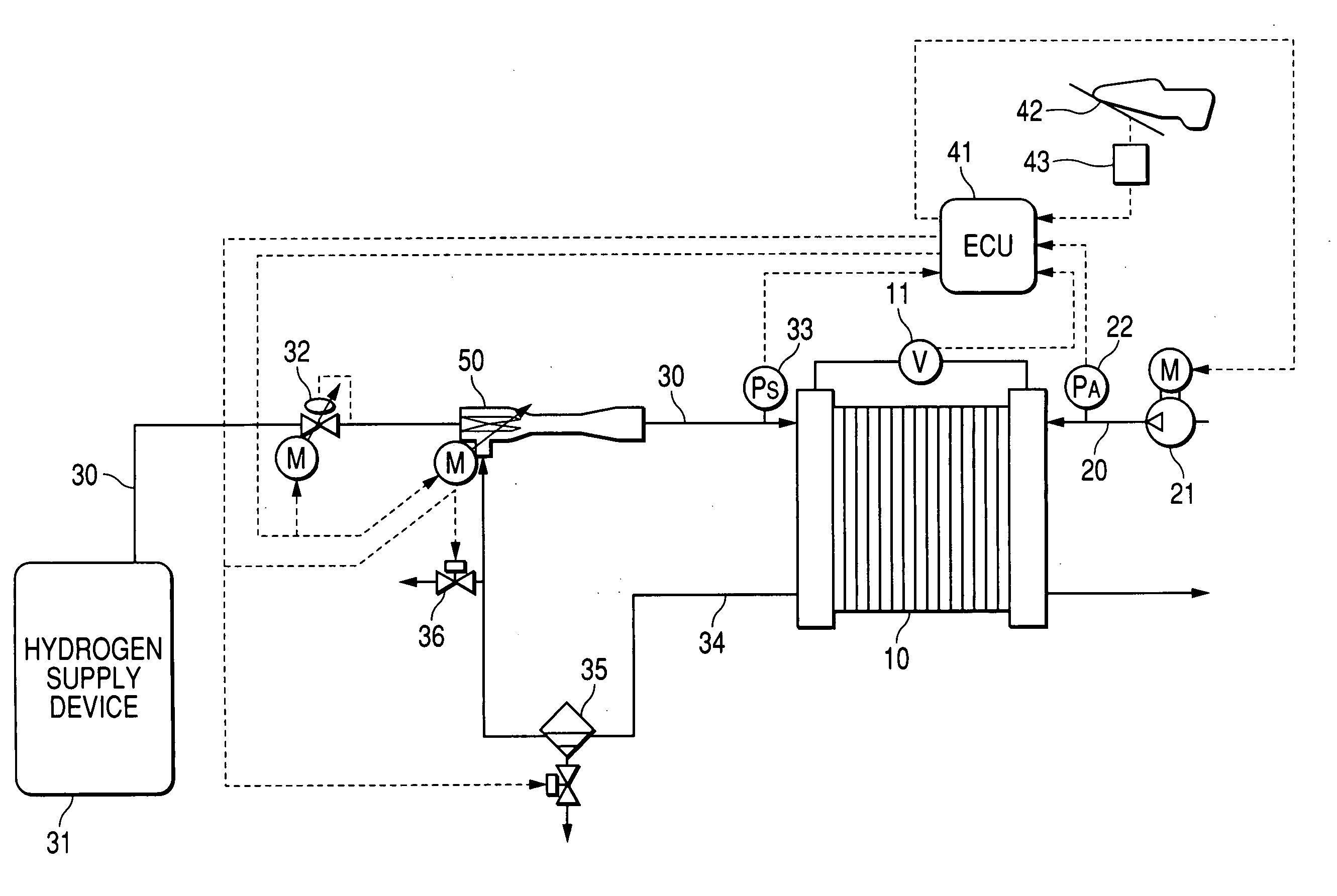
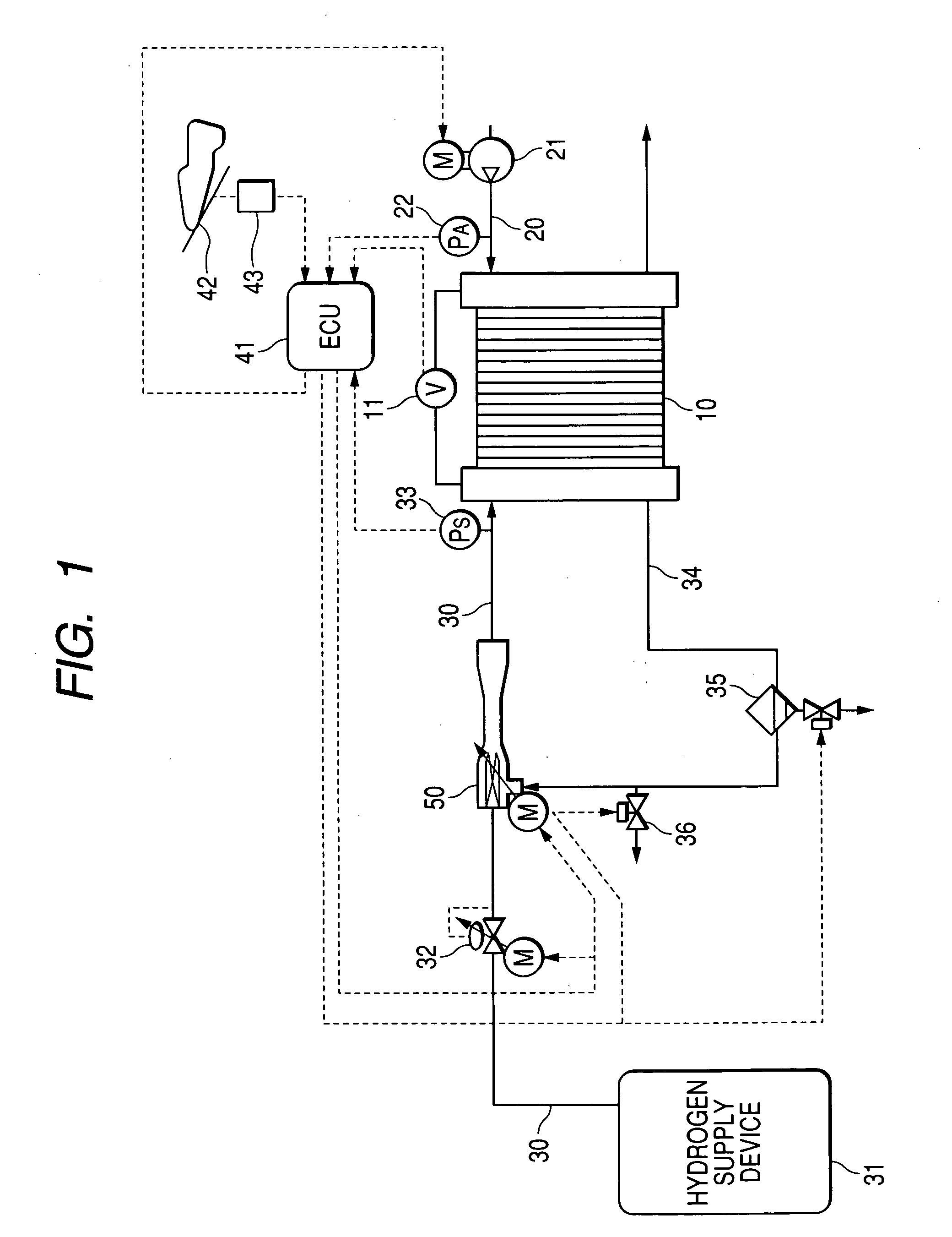
[0033] Referring to the drawings, wherein like reference numbers refer to like parts in several views, particularly to FIG. 1, there is shown a fuel cell system equipped with a fuel supply system according to the invention which is employed in an electric automobile driven by fuel cells. The fuel cell system consists essentially of a fuel cell stack 10, an air supply device 21, a fuel supply device 31, an ejector device 50, and a controller 41. The ejector device 50 may be implemented by an ejector vacuum pump and will be referred to as an ejector vacuum pump 50 below.

[0034] The fuel cell stack 10 works to convert the energy produced by electrochemical reaction of hydrogen (i.e., fuel) and oxygen (i.e., oxidizing agent) into electric power. The fuel cell stack 10 is made up of a plurality of solid polyelectrolyte fuel cells (PEFCs). Each cell is made up of a pair of electrodes (will also called an oxygen and a fuel electrode below) and an electrolyte film disposed between the electr...

second embodiment

[0064]FIG. 4 shows a fuel supply system according to the invention. The fuel supply system includes a humidity sensor 37 which measures the humidity H of the mixture of the hydrogen gas and the off-gas flowing through a portion of the hydrogen supply line 30 downstream of the ejector vacuum pump 50. The controller 41 works to control the recirculated off-gas flow rate Ge as a function of the humidity H, as measured by the humidity sensor 37, to bring the humidity H into agreement with a target humidity Hn required by the fuel cell stack 10 (i.e., the amount of moisture to be added to the fuel cell stack 10).

[0065] The required humidity Hn depends upon a power generating condition (e.g., the generated current) of the fuel cell stack 10. The controller 41 determines the required humidity Hn and controls the amount of the off-gas containing moisture to adjust the humidity H, as measured by the humidity sensor 37, to the required humidity Hn. Other arrangements and operations of the fue...

fourth embodiment

[0068]FIG. 6 shows a fuel supply system according to the invention which is different from the above embodiments in that a temperature sensor 38 is installed in the off-gas recirculating line 34 to measure the temperature T of the off-gas, and the controller 41 controls the recirculated off-gas flow rate Ge as a function of the temperature T to bring the humidity of the B e supplied to the fuel cell stack 10 into agreement with the required humidity Hn.


PUM


Abstract

A fuel supply system for use in a fuel cell system which includes a controller, a pressure regulator, and an ejector device. The controller controls the pressure of a main flow of fuel gas outputted from the pressure regulator and the position of an ejector nozzle of the ejector vacuum pump as a function of electricity generated by a fuel cell to adjust a flow rate of an off-gas to be recirculated to the fuel cell. This structure eliminates the need for an additional flow regulator to regulate the flow rate of the off-gas, thereby ensuring the stability in controlling the flow rate of the off-gas to be recirculated.

Description

CROSS-REFERENCE TO RELATED APPLICATION [0001] The present application claims the benefit of Japanese Application No. 2003-362484, which was filed on Oct. 22, 2003, the disclosure of which is hereby incorporated by reference. BACKGROUND OF THE INVENTION [0002] 1 Technical Field of the Invention [0003] The present invention relates generally to a fuel supply system working to mix a fuel gas discharged from a fuel cell (i.e., an off-gas) with a main supply of fuel stream and recirculate it to the fuel cell, and more particularly to such a fuel supply system designed to ensure the stability in regulating a flow rate of the off-gas to be recirculated. [0004] 2 Background Art [0005] There are known fuel cell systems designed to suck the off-gas discharged from a fuel electrode of a fuel cell using a pump and mix it with a main supply of fuel gas for recirculating the off-gas to the fuel cell. The pump is usually implemented by an ejector vacuum pump equipped with an ejector nozzle since i...

Claims


Application Information

Patent Timeline
IPC IPC(8): H01M2/02H01M8/04H01M8/10
CPCH01M8/04097Y02E60/50H01M8/04141H01M8/04343H01M8/04388H01M8/04395H01M8/04447H01M8/04514H01M8/04559H01M8/04753H01M8/04761H01M8/04798H01M8/04835H01M8/0488H01M2008/1095H01M8/04104
Inventor HIRAMATSU, HIDEHIKOYAMAMOTO, TAKESHIMORISHIMA, SHINGO
Owner DENSO CORP
Why Eureka
Try Eureka