Implantable device delivery system handle and method of use

a technology of implantable medical devices and handle, which is applied in the field of delivery systems, can solve the problems of requiring additional personnel, clumsy process of handling scopes and delivery catheters, etc., and achieve the effects of facilitating user's ability to tighten and loosen the scope, facilitating ease and accuracy of deployment, and enhancing physician control

Active Publication Date: 2009-05-07
MERIT MEDICAL SYST INC
View PDF32 Cites 45 Cited by
  • Summary
  • Abstract
  • Description
  • Claims
  • Application Information

AI Technical Summary

Benefits of technology

[0007]It is a principal purpose of the present invention to provide a delivery system for implantable devices that facilitates ease and accuracy of deployment. In accordance with an exemplary embodiment of the present invention, a delivery system is provided that allows the physician to concentrate on correct placement without having to estimate extent of deployment. In particular, in a preferred embodiment, the present device has a physical safety mechanism that limits deployment to the critical deployment point (e.g., predetermined length proportional to the length of the implantable device being deployed). The critical deployment point may range from 5% to 95% of the implantable devices length and the optimal length is relative based on the length of the implantable device. At this point, if the physician is satisfied with placement, she can engage the safety means to what we refer to as the Proceed Orientation (PO) and fully deploy the implantable medical appliance. Alternative safety systems in accordance with the invention include but are not limited to removable tab stops, ratchet incremental stops, etc., that allow for deployment and implantable device realignment along a continuum.
[0008]Another objective of an exemplary embodiment in accordance with the present invention is to provide a delivery system that allows for the one handed placement of large implantable devices generally and stents of about 50 mm or larger, in particular.
[0009]Still another objective in accordance with a preferred embodiment of the present invention is to provide a delivery device having direct visualization capabilities directly incorporated into the device by allowing for the passage of the scope through the internal diameter of the delivery device.
[0010]Yet another objective in accordance with an exemplary embodiment of the present invention is to provide a delivery system handle that releasably engages the scope lumen in order to provide enhanced physician control. In line with this objective, preferred embodiments facilitate the user's ability to tighten and loosen the scope with the same hand that actuates the safety mechanism by making the respective items available to different phalanges of the users hand.
[0011]In addition to the above objectives, an exemplary deployment system preferably has one or more of the following characteristics: (1) biocompatible; (2) compliant with specialized radially expanding implantable devices; (3) capable of distal or proximal medical appliance release; (4) smooth and clean outer surface; (5) length of the device variable according to the insertion procedure to be employed; (6) outer dimension as small as possible (depends on the diameter of crimped medical appliance); (7) dimensions of the device must offer enough space for the crimped implantable devices; (8) sufficient flexibility to adapt to anatomical curvatures without loss of ability to push or pull; (9) low friction between the moving parts; (10) sufficient resistance to kinking; (11) good deployment force, ability to reposition partially deployed medical appliance; and (12) sufficiently economical to manufacture so as to make the deployment apparatus disposable.

Problems solved by technology

Unfortunately, handling the scope and the delivery catheter can often be a clumsy process when the two devices easily disassociate from each other.
Moreover, since many delivery catheters, for one reason or another, cannot be adequately managed with one hand, additional personnel are required when handling the scope and the delivery catheter.

Method used


Image

  • Implantable device delivery system handle and method of use
  • Implantable device delivery system handle and method of use
  • Implantable device delivery system handle and method of use

Examples


Embodiment Construction

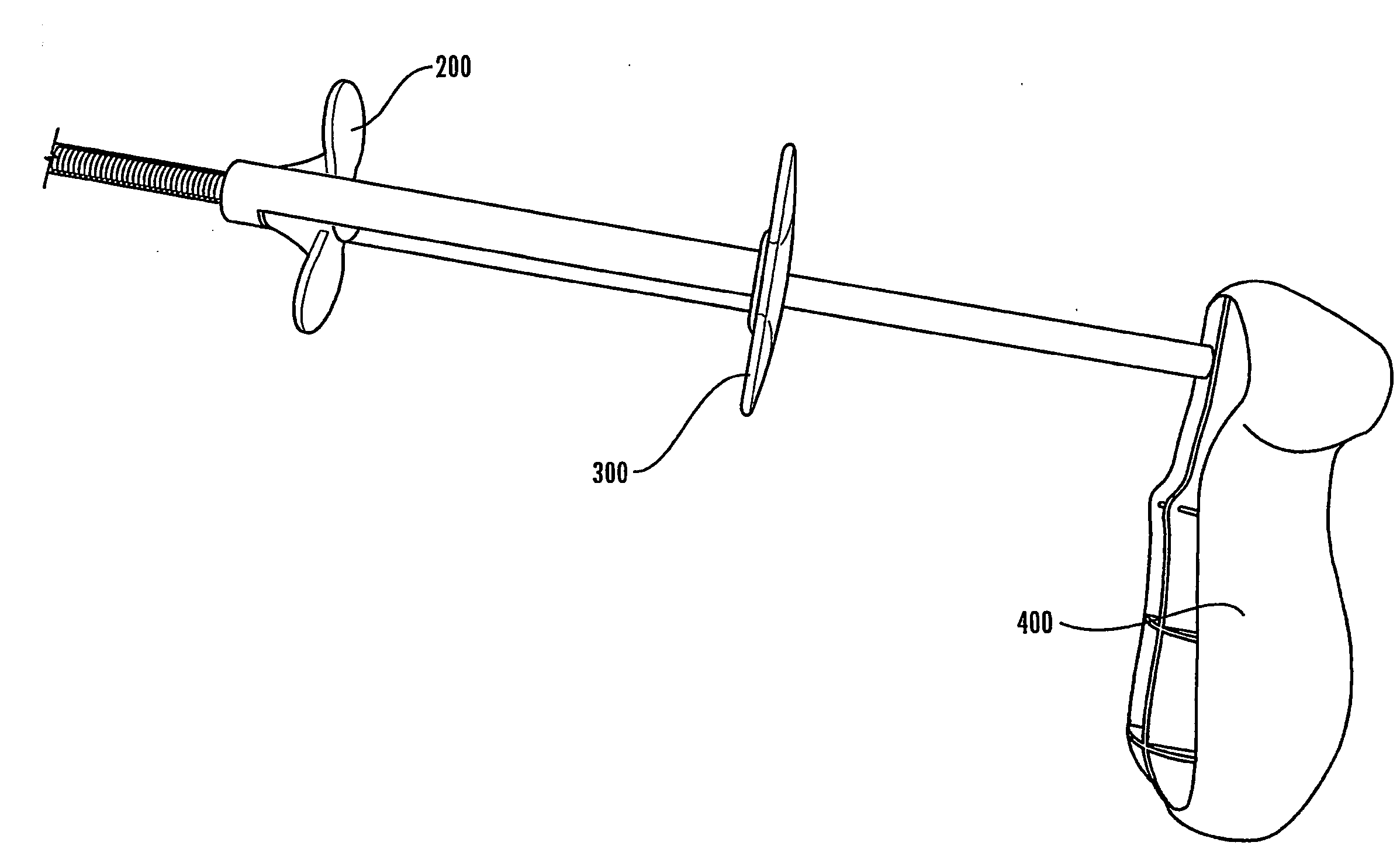
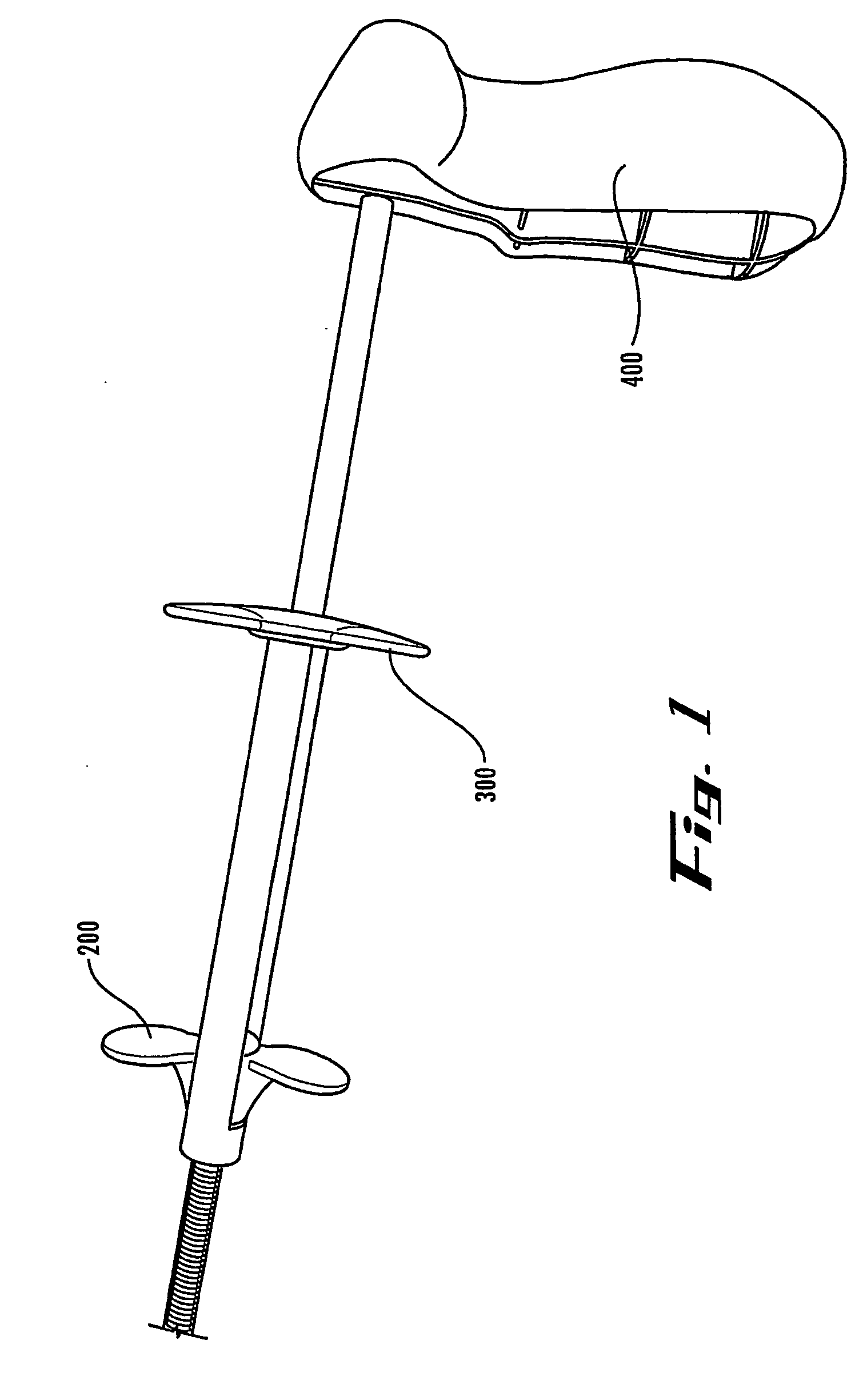
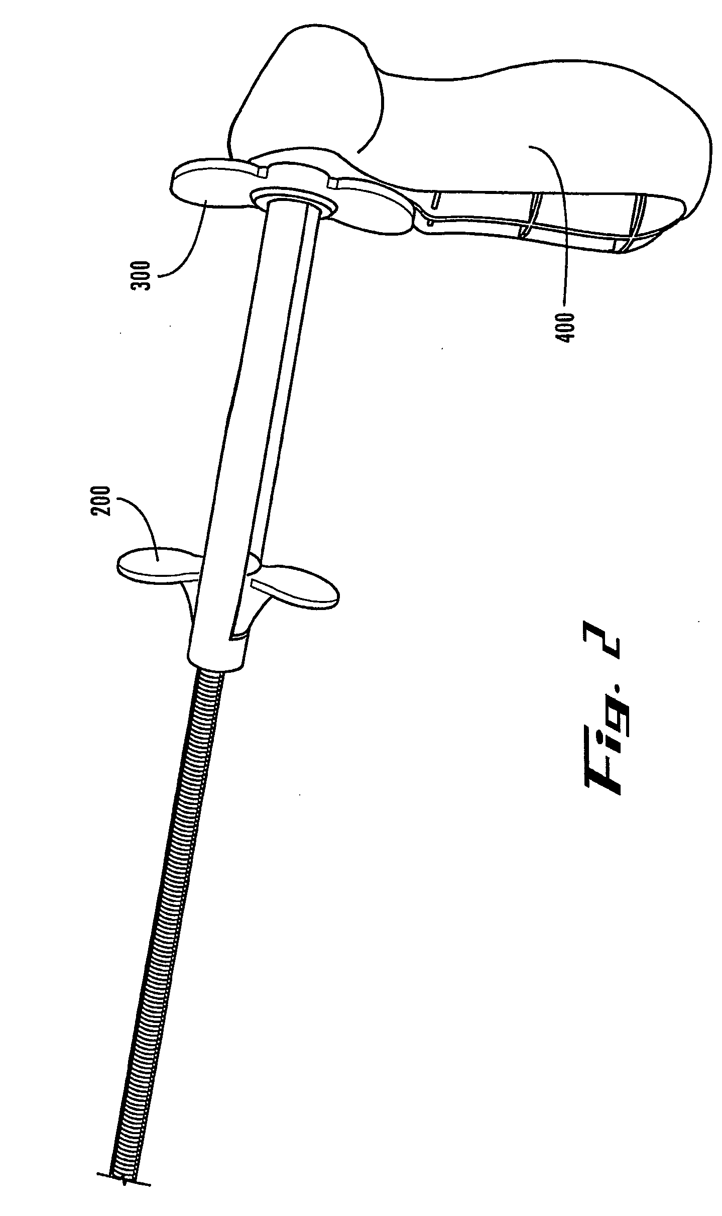
[0004]According to the present invention, a device is provided for allowing a user to deploy a stent in an anatomical lumen of a patient. The stent deployment device comprises a stabilizing member, a longitudinally extending outer tubular member having distal and proximal ends, and a longitudinally extending inner tubular member having distal and proximal ends, the distal end of the inner tubular member comprising a tip. The inner tubular member is coupled with the stabilizing member and at least a portion of the inner tubular member is disposed within the outer tubular member such that the inner tubular member is longitudinally and axially displaceable relative to the outer tubular member. A deployment mechanism is coupled with the outer tubular member. The deployment mechanism comprises a release member for longitudinally moving the outer tubular member relative to the inner tubular member.

[0005]Also according to the present invention, a stent delivery system is provided for use i...


PUM


Abstract

The present invention, in an exemplary embodiment, provides a delivery system and novel handle configuration for the delivery system that facilitates repeatable placement of implantable devices. In particular, in optical embodiments, the handle allows for the reversible coupling of scopes directly to the handle to enhance physician control during placement. The delivery system also allows for one-handed manipulation as finger action can be used to engage and disengage the scope as well as actuate the extent of implantable device deployment. Exemplary delivery systems are flexible, durable and/or assure proper installation of one or more implantable devices in a single procedure. Moreover, the preferred embodiments of the delivery system provides for the reloading of the delivery device with additional implantable devices for additional interventional procedures, resulting in a substantially reusable delivery device.

Description

FIELD OF INVENTION[0001]The present invention relates generally to delivery systems directed to implantable medical devices and more particularly to specialized handles for allowing scope introduction and locking and one-hand implantable device placement and delivery.BACKGROUND OF THE INVENTION[0002]Interventional practitioners, regardless of subspecialty have always had to demonstrate profound dexterity in order to effectively and accurately perform invasive procedures. This is particularly the case with the delivery and deployment of implantable devices where there is very little room for error with respect to placement. In order to assist with placement accuracy, many interventionalists utilize scopes, such as bronchoscopes. Unfortunately, handling the scope and the delivery catheter can often be a clumsy process when the two devices easily disassociate from each other. Moreover, since many delivery catheters, for one reason or another, cannot be adequately managed with one hand,...

Claims


Application Information

Patent Timeline
Patent Type & Authority Applications(United States)
IPC IPC(8): A61B19/00A61F11/00A61F2/06A61F2/84
CPCA61F2/95A61F2002/9517A61F2/966A61F2/9517
Inventor MANGIARDI, ERICREYNOLDS, JASONBORG, ULF
Owner MERIT MEDICAL SYST INC
Why Eureka
Try Eureka