
Bifurcated oil scavenge system for a gas turbine engine

a gas turbine engine and scavenging system technology, applied in the direction of engines, machines/engines, mechanical equipment, etc., can solve the problems of increased oil leakage potential, increased oil leakage from the compartment, and disadvantages of conventional scavenging port arrangements

Active Publication Date: 2006-02-14
RTX CORP
View PDF8 Cites 58 Cited by
  • Summary
  • Abstract
  • Description
  • Claims
  • Application Information

AI Technical Summary

Benefits of technology

This solution ensures efficient direction of the two-phase air / oil mixture without oil leakage across all operating conditions, reducing the risk of contamination and maintaining optimal performance in compact high-speed bearing compartments.

Problems solved by technology

Failing to remove or scavenge oil from the bearing may be as detrimental to the bearing as insufficient oil flow because the churning of unscavenged oil within the bearing can rapidly lead to overheating.
Although effective for particular compartment sump dimensions and moderate rotational speeds, as engine core size constraints become more aggressive and speeds increase, disadvantages of conventional scavenge port arrangements may begin to occur.
The reduced separation may increase the potential for oil leakage.
Furthermore, interfacial shear acting on the gas / liquid interface may drive oil away from the drain at BDC.
Oil recirculation zones tend to contaminate seals, which may ultimately result in oil leakage from the compartment.

Method used


Image

  • Bifurcated oil scavenge system for a gas turbine engine
  • Bifurcated oil scavenge system for a gas turbine engine
  • Bifurcated oil scavenge system for a gas turbine engine

Examples


Embodiment Construction

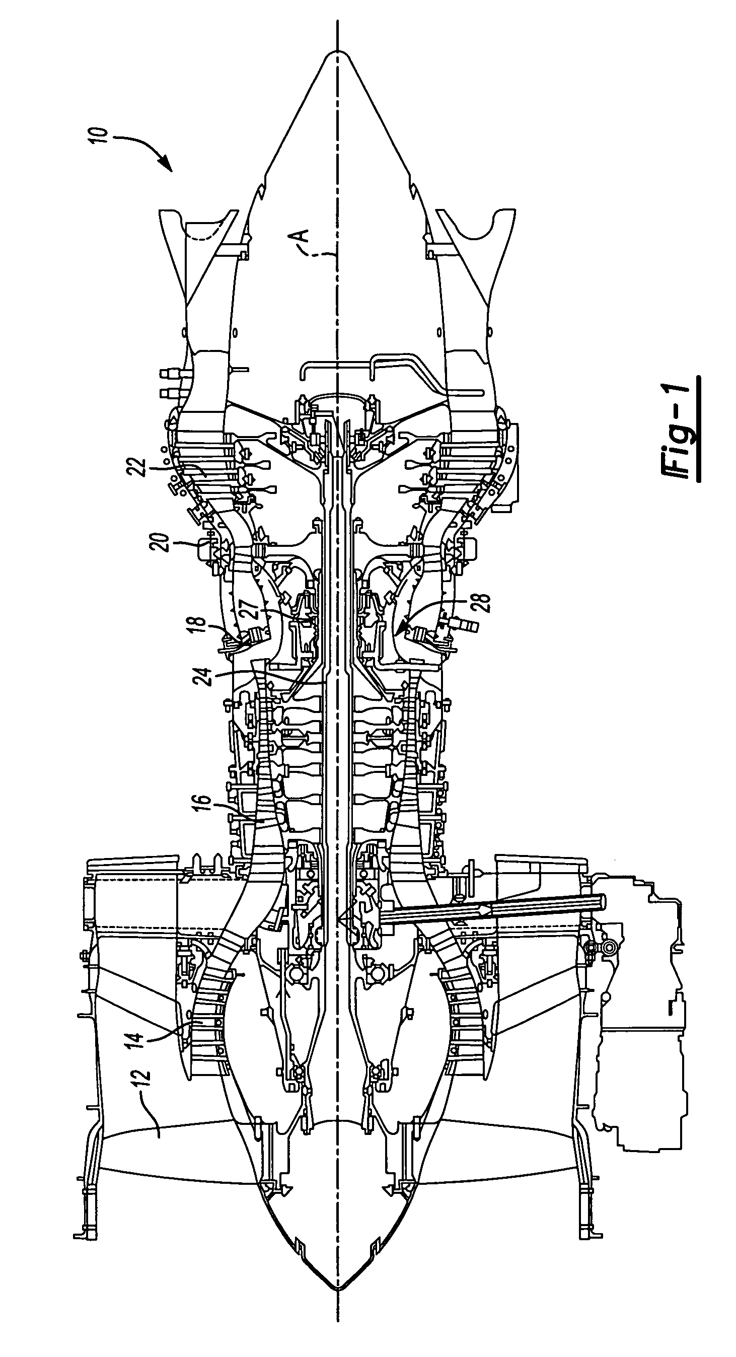
[0019]FIG. 1 illustrates a general schematic sectional view of a gas turbine engine 10. The gas turbine engine 10 is defined about an engine centerline A about which the various engine sections rotate. Generally, the engine 10 includes a fan section 12, a low pressure compressor section 14, a high pressure compressor section 16, a combustor section 18, a high pressure turbine section 20 and a low pressure turbine section 22. It should be understood that although a particular arrangement is disclosed in the illustrated embodiment, other arrangements will benefit from the instant invention.

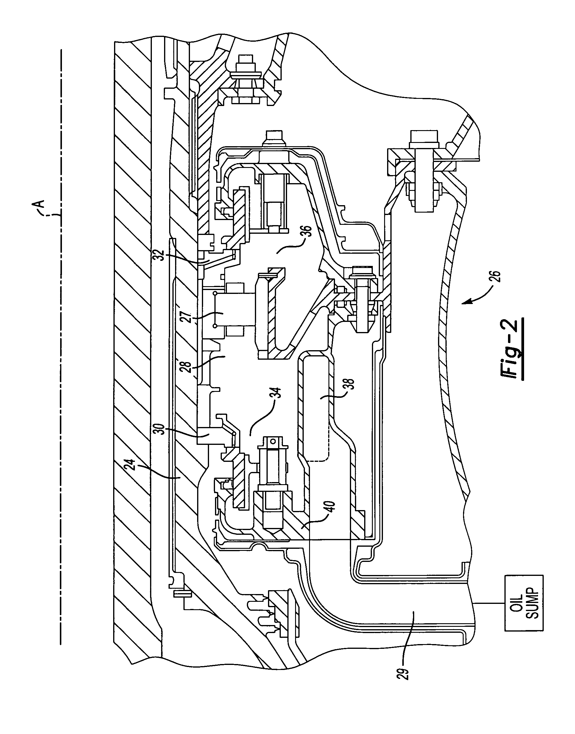
[0020]The sections are mounted about a main shaft 24 supported by various high speed bearings. One bearing 27 is located within a mid bearing compartment 28. The bearing 27 and compartment 28 receives lubrication and cooling from oil which is provided through jets and is then collected through an oil scavenge system which returns the oil to an oil sump through a flow path 29 (FIG. 2). It should be u...


PUM


Abstract

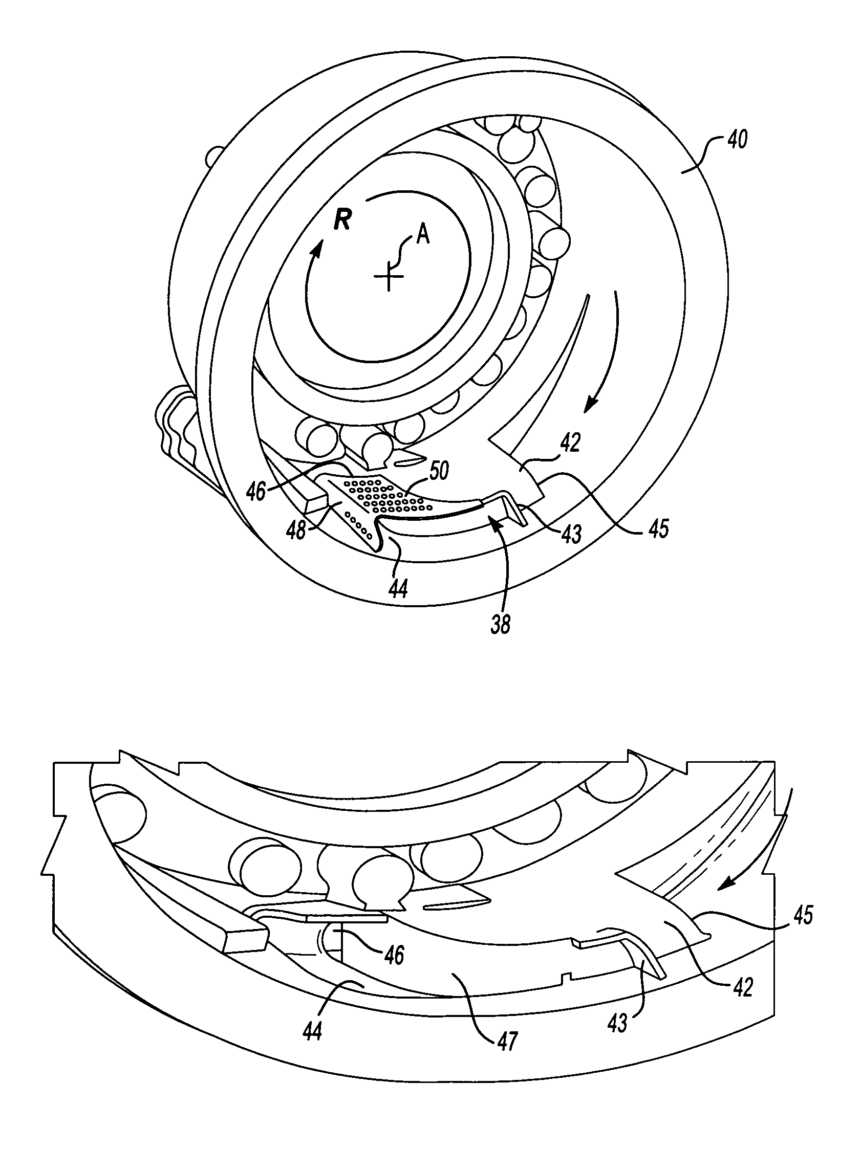
An oil scavenge system includes a tangential scavenge scoop and a settling area adjacent thereto which separately communicate with a duct which feeds oil into an oil flow path and back to an oil sump. A shield is mounted over the settling area to at least partially shield the collecting liquid oil from interfacial shear. A multiple of apertures are located through the shield to permit oil flow through the shield and into the duct. The scavenge scoop forms a partition which separates the duct into a first portion and a second portion. The first portion processes upstream air / oil mixture that is captured by the tangential scoop while the second portion receives the oil collected in the settling area.

Description

BACKGROUND OF THE INVENTION[0001]The present invention relates to oil systems for gas turbine engines, and more particularly to an oil scavenge system.[0002]Gas turbine engines employ high-speed bearings that require a continuous supply of oil for lubrication and cooling. For optimum performance, the oil flow must be properly directed into and away from the bearings. Failing to remove or scavenge oil from the bearing may be as detrimental to the bearing as insufficient oil flow because the churning of unscavenged oil within the bearing can rapidly lead to overheating.[0003]In a conventional lubrication system, oil is supplied to the rolling elements of the bearings under pressure and then relies on gravity or its dynamics to drain back to a reservoir.[0004]One effective way to accomplish the return flow is to maintain an open, straight, and unrestricted passageway from the bearing back to the sump. This often requires that the air / oil mixture be redirected from a circumferential pat...

Claims


Application Information

Patent Timeline
Patent Type & Authority Patents(United States)
IPC IPC(8): F02C7/06F01D25/16F01D25/00F01D25/18F02K3/06
CPCF01D25/18F05D2260/602F05D2260/60F16C33/6685F16C2360/23
Inventor PETERS, ROBERT E.MESSERSCHMIDT, DWAYNEGLAHN, J. AXELALLARD, KENNETH L.JEN, HSIANMIN F.SPIRES, LARRY W.BARNSBY, ROGER M.
Owner RTX CORP
Learn More