
Heat exchanger and use thereof in showers

a technology of heat exchanger and shower head, which is applied in the direction of heat exchanger conduit, heat exchanger type, domestic hot water supply system, etc., can solve the problems of wasting energy, substantial amount of hot water being lost down the drain, and not providing the necessary equipment for showering, etc., to achieve the effect of improving mixing and heat transfer efficiency

Inactive Publication Date: 2008-01-03
NOBILE JOHN R
View PDF21 Cites 59 Cited by
  • Summary
  • Abstract
  • Description
  • Claims
  • Application Information

AI Technical Summary

Benefits of technology

[0012] In certain embodiments, the first conduit is formed with helical convolutions in the outer surface, such that the external surface of these convolutions, when combined with a surrounding smooth tubular member, will form the second conduit means, thus placing the two conduit means in intimate thermal contact with each other. The convolutions in the wall of the first conduit also serve to impart turbulence to the drain water passing therethrough, thus increasing the convective heat transfer from the drain water to the wall of the conduit. The convolutions in the wall of the first conduit also serve to impart a spiraling flow to the drain water passing through, thus increasing the velocity of the flow and therefore increasing the rate of convective heat transfer from the drain water to the wall of the conduit.
[0029] It is another objective of this invention to provide a design that has the highest possible efficiency for its size and for the amount of material used in its construction.

Problems solved by technology

There is hardly any form of habitation, whether personal residences, commercial habitations, or miscellaneous bathing facilities, that does not provide the necessary equipment for showering.
Despite the fact that showers of reasonable length and temperature may consume less hot water than bathing in a tub, the fact remains that a substantial amount of hot water is lost down the drain, since the shower water remains in the shower installation for only a very brief period of time, in which only a small portion of it's heat energy is utilized.
This, of course, is wasted energy, and represents an expense in fuel or electricity to heat the water which could be substantially reduced if some of the unused heat in the waste water could be recaptured and put to use.
None of these devices, however, would be practical or effective in the application of recovering heat from the waste water passing through the drain conduit of a shower installation because of the unique environment and requirements of such a system, such as not interfering with the free flow of drain water, not being conducive to clogging, being easy to clear in the event of a clog using standard methods, adapting to existing standard plumbing fittings, and fitting into the typically available space.
U.S. Pat. No. 5,791,401 discloses a heat recovery device for personal showers, however the designs disclosed therein are expensive to manufacture because of the complex assembly process, and the inefficient use of materials, and the device has a low operating efficiency.

Method used


Image

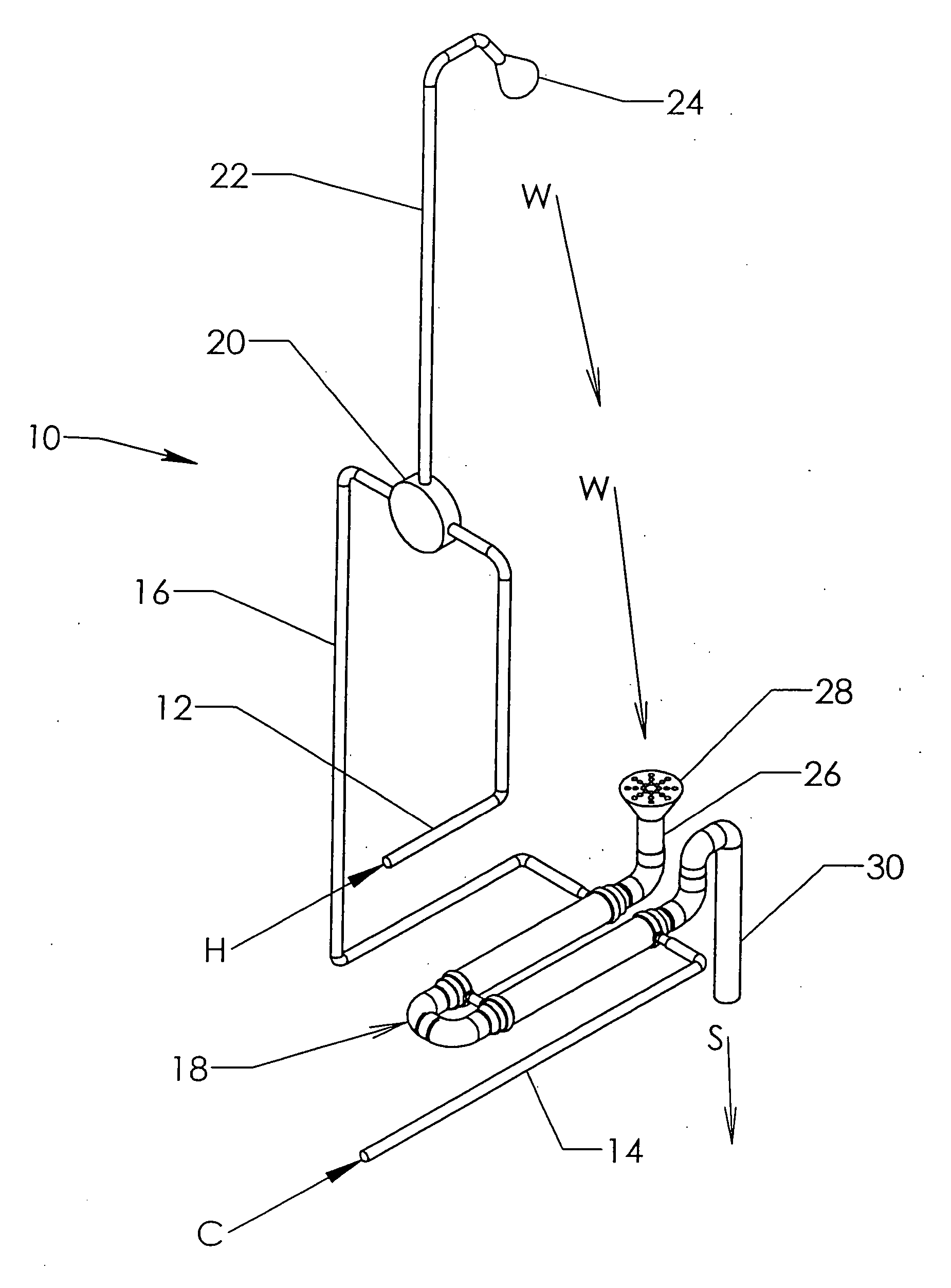
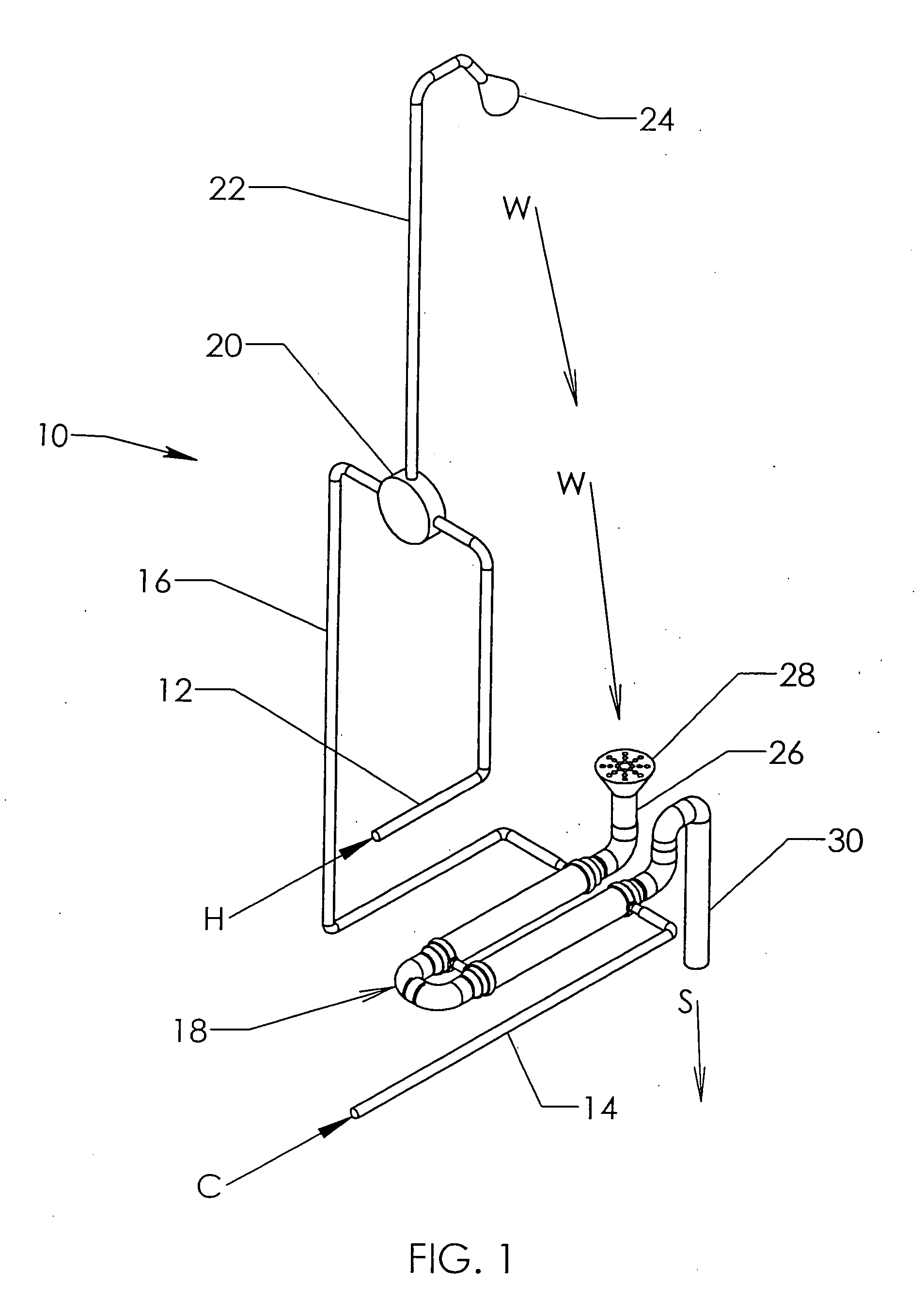
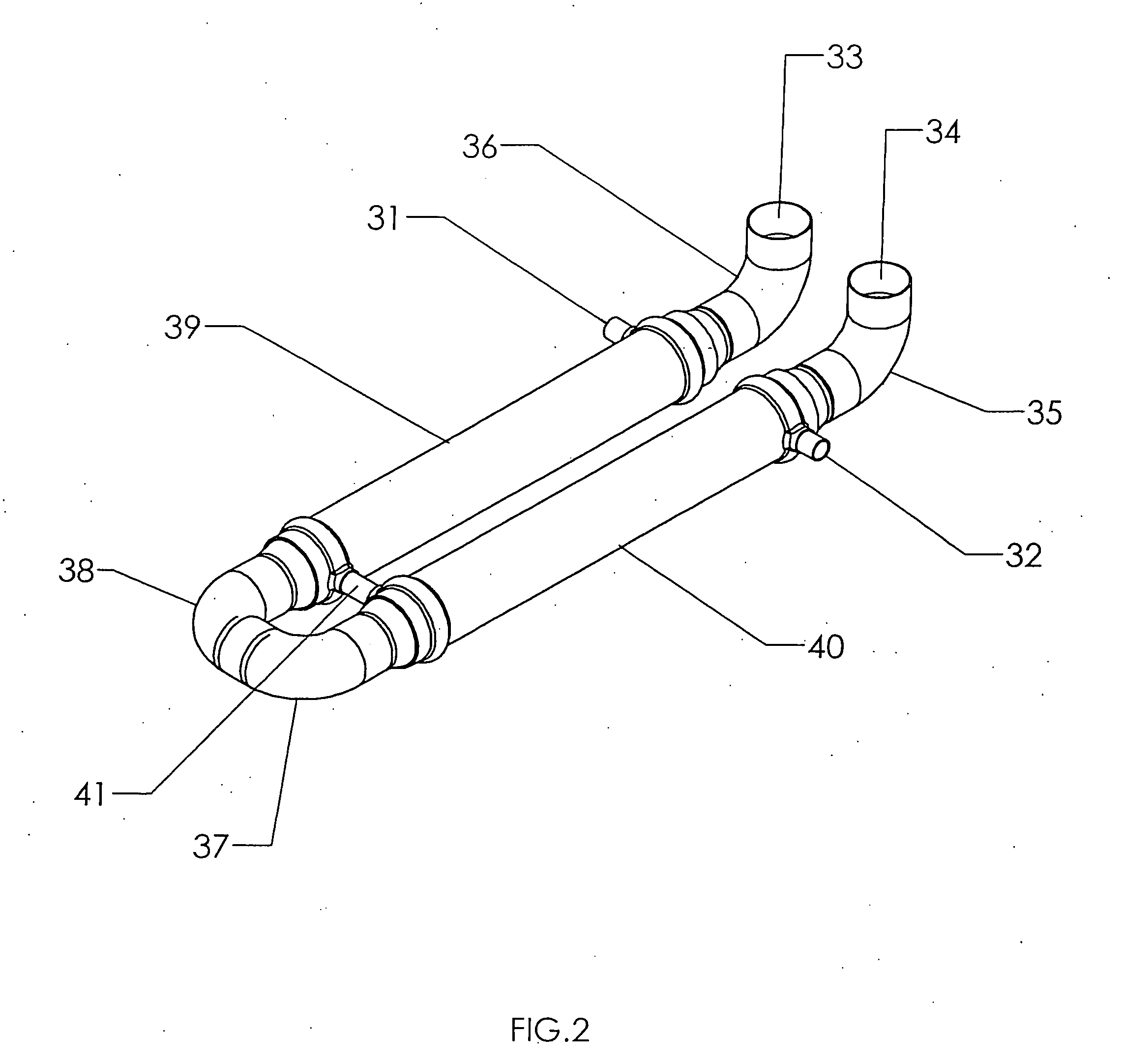
  • Heat exchanger and use thereof in showers
  • Heat exchanger and use thereof in showers
  • Heat exchanger and use thereof in showers

Examples


example

[0072] A heat exchanger of the general design depicted in FIG. 8 (without the sleeve layer 47 shown in FIGS. 6 and 7) was constructed from copper. The first (inner) conduit was 92 centimeters long, formed from a single first copper tube having an inner diameter of 1.5 inches and a wall thickness of 0.080 inches. Symmetrical helical convolutions were generated by a hydroforming process wherein the first copper tube was placed in a die containing the desired geometry of the desired convolutions, and expanded from the interior using a pressurized fluid against said die. Thus, the first copper tube took the outer shape corresponding to the die shape. The inner diameter of the thus convoluted first conduit ranged from 3.8 to 5.1 centimeters, with a helical pitch of 1.25 inches. The convoluted first conduit was then inserted into a single second copper tube (corresponding to feature 42 in FIG. 8) having a wall thickness of 0.058 inches, wherein the inner diameter was equal to or slightly ...


PUM


Abstract

An improved heat exchanger design is disclosed. The design of the heat exchanger provides for a safe separation of the flow streams even in the event of leakage. An improved heat recovery device for use in the drain conduit of standard shower installations, comprising the heat exchanger of the invention, is also disclosed.

Description

RELATED APPLICATIONS [0001] This application claims priority from U.S. Provisional Patent Application Ser. No. 60 / 815,773, filed Jun. 22, 2006, which is hereby incorporated by reference in its entirety.FIELD OF THE INVENTION [0002] This invention relates generally to the field of heat exchangers, and more particularly to a heat exchanger for use in a personal shower environment which recaptures heat from waste water passing through the shower drain and distributes that heat into the cold water entering the shower to raise the temperature of the cold water and thus reduce the amount of hot water required to maintain a given shower temperature. BACKGROUND OF THE INVENTION [0003] This invention relates generally to the field of heat exchangers, and more particularly to a heat exchanger for use in a shower environment which recaptures heat from waste water passing through the shower drain and distributes that heat into the cold water entering the shower to raise the temperature of the c...

Claims


Application Information

Patent Timeline
Patent Type & Authority Applications(United States)
IPC IPC(8): F24D17/00F28D7/14
CPCE03C1/00E03C2001/005F24D17/0005F28D7/14F28F1/003F28F1/06F28F1/08F28F2210/06Y02B30/566F28D21/0012Y02B30/18Y02B30/56
Inventor NOBILE, JOHN R.
Owner NOBILE JOHN R
Learn More