
Automotive radar with radio-frequency interference avoidance

a technology of radio frequency interference and radar system, which is applied in the direction of using reradiation, measuring devices, instruments, etc., can solve the problems of unreliable obstacle detection, poor estimation of ramie and velocity, and high cost of vehicle maintenance and repair, so as to suppress man-made interference and improve the estimation of range and velocity in the automotive fmcw radar system.

Active Publication Date: 2013-06-25
MITSUBISHI ELECTRIC CORP
View PDF23 Cites 50 Cited by
  • Summary
  • Abstract
  • Description
  • Claims
  • Application Information

AI Technical Summary

Benefits of technology

The patent text explains how to improve the detection of distance and speed in an automotive FMCW radar system. This is done by identifying and eliminating interference caused by humans. The technical effect of this invention is to improve the accuracy and reliability of automotive radar systems.

Problems solved by technology

170-181, February 2007, has shown that the sweep patterns and associated signal processing techniques commonly used in automotive radar are all susceptible to multiuser interference.
Known automotive FMCW radar systems operating in multiuser environments therefore provide unreliable obstacle detection and poor estimation of ramie and velocity due to the problems caused by multiuser interference.

Method used


Image

  • Automotive radar with radio-frequency interference avoidance
  • Automotive radar with radio-frequency interference avoidance
  • Automotive radar with radio-frequency interference avoidance

Examples


example configuration

[0257]An example configuration of an interference classifier ICR 203 for implementing the above-described advantageous interference classification is described below.

[0258]FIG. 9 is a functional block diagram of the interference classifier ICR 203. The classifier ICR 203 comprises the following blocks:[0259]a data buffer BFR 802[0260]a normaliser NRM 804[0261]a scale factor calculator SCL 803[0262]a nonlinear transformer NLT 805[0263]an averaging circuit AVG 806[0264]a comparator CMR 807.

[0265]The operation interference classifier ICR 203 is described below.

[0266]A number K of signal samples x1, x2, . . . , xk, . . . , xK forming a data block under examination are transferred via input BX to the data buffer BFR 802.

[0267]Samples, available at output XX are used by the scale factor calculator SCL 803 to determine a scale factor SC, such as the mean absolute deviation MA or the standard deviation SD. The selected type of normalisation is set via input ST of the scale factor calculator...


PUM


Abstract

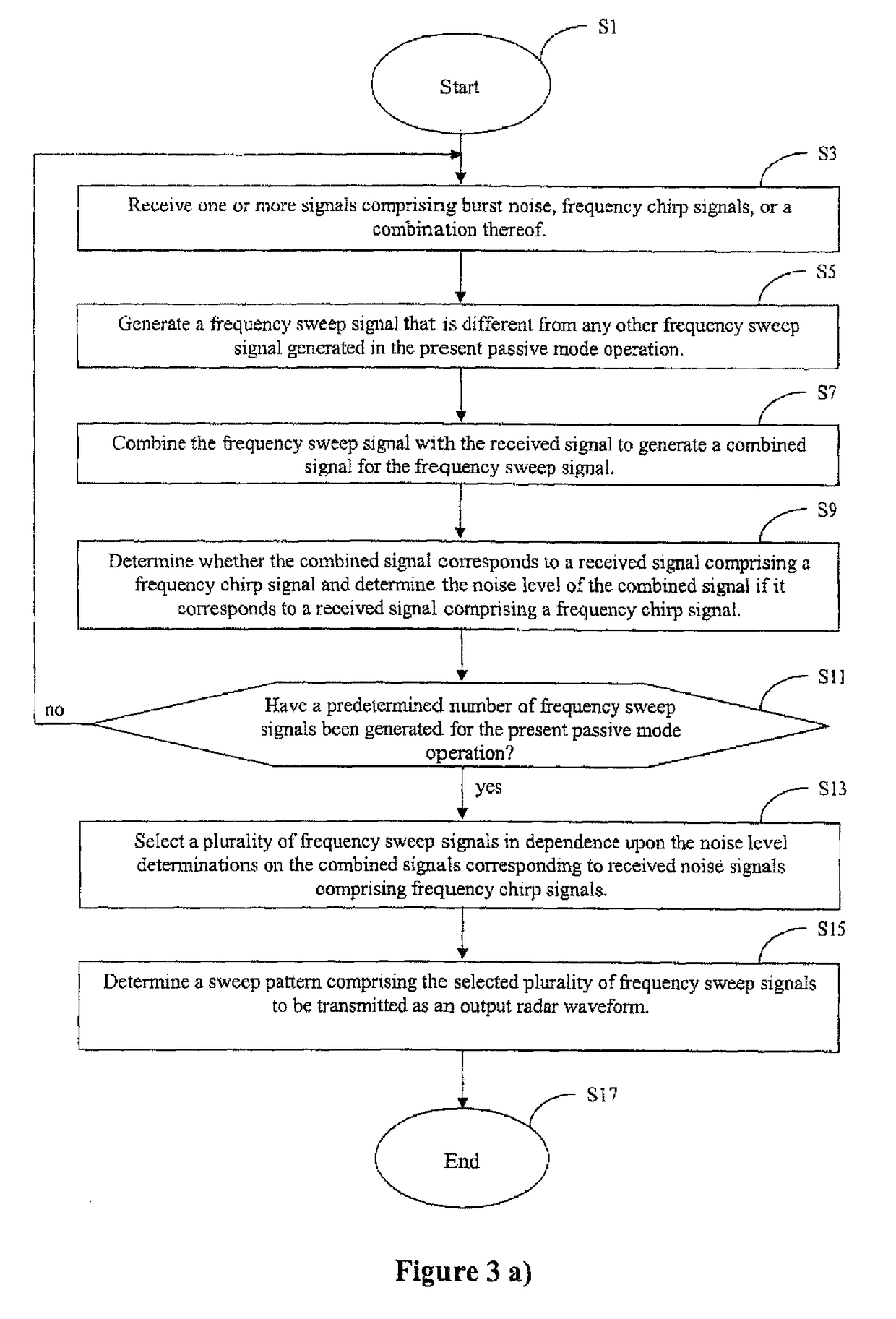
An automotive radar system to determine a sweep pattern to be transmitted as an output radar waveform in a multiuser transmission environment is disclosed. The system includes: a receiver to receive noise signals; a signal generator to generate a plurality of different frequency sweep signals; a signal combiner to combine each frequency sweep signal with a received noise signal; an interference classifier to identify combined signals corresponding to one or more received noise signals including frequency chirp signals and to determine the respective noise levels of the identified combined signals corresponding to one or more received noise signals including frequency chirp signals; a selector to select a plurality of frequency sweep signals in dependence upon the noise levels determined by the interference classifier; and a control unit to determine a sweep pattern comprising the selected plurality of frequency sweep signals to be transmitted as an output radar waveform.

Description

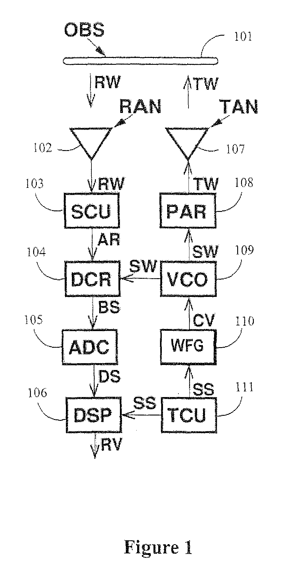
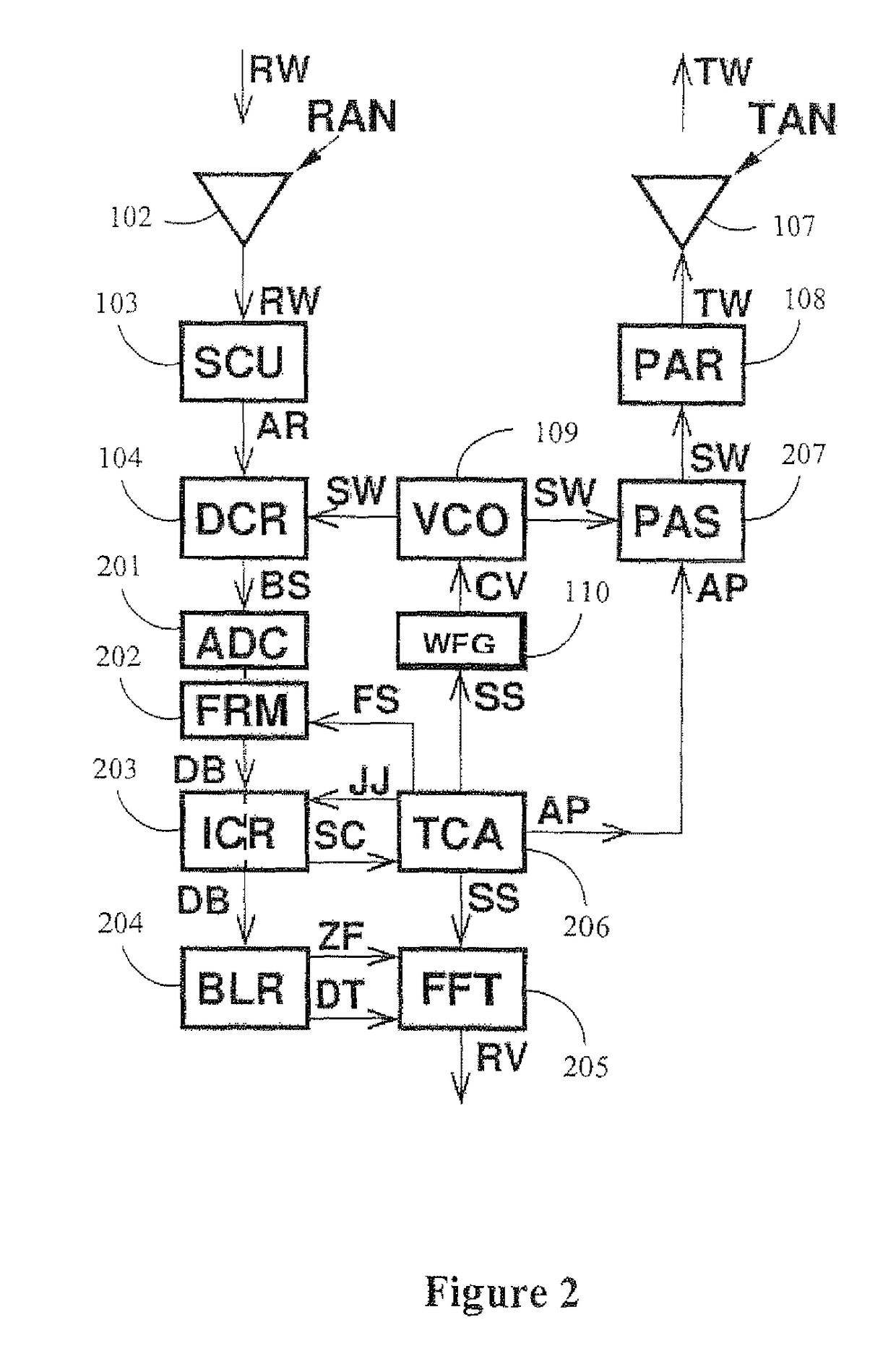
CLAIM TO PRIORITY[0001]The present application claims priority from European patent application number 10164048.0 filed on 27 May 2010, the full contents of which are incorporated herein by cross-reference.FIELD OF THE INVENTION[0002]The present invention relates to an automotive radar system and method for use in detecting and suppressing the effects of interference. The disclosed system and method are particularly applicable to improving the resistance of frequency modulated continuous-wave (FMCW) automotive radar to interference caused by other FMCW systems that operate in the same region and share the same frequency band.BACKGROUND OF THE INVENTION[0003]FIG. 1 is a simplified functional block diagram of conventional frequency modulated continuous-wave (FMCW) automotive radar.[0004]The system comprises a receive antenna RAN 102, a signal conditioning unit SCU 103, a down-converter DCR 104, an analogue-to-digital converter ADC 105, a digital signal processor DSP 106, a timing / cont...

Claims


Application Information

Patent Timeline
Patent Type & Authority Patents(United States)
IPC IPC(8): G01S13/00G01S13/931
CPCG01S7/023G01S13/931G01S13/34G01S7/36G01S7/0232
Inventor SZAJNOWSKI, WIESLAW JERZY
Owner MITSUBISHI ELECTRIC CORP
Learn More