Forced extension caster assembly

a technology of casters and assemblies, applied in the field of caster assemblies, can solve the problems of still passing testing, increasing labor costs, and increasing the difficulty of occupying racks, so as to facilitate the placement of multiple racks, eliminate safety concerns, and store easily out of the way of the racks

Inactive Publication Date: 2009-01-20
LENOVO GLOBAL TECH INT LTD
View PDF14 Cites 12 Cited by
  • Summary
  • Abstract
  • Description
  • Claims
  • Application Information

AI Technical Summary

Benefits of technology

[0005]The present invention offers a solution for making rack installation and relocation feasible, safe and economical.
[0006]It is an aspect of an embodiment of the present invention to provide a pemanently attached caster assembly that will not be misplaced.
[0007]It is a further aspect of an embodiment of the present invention to provide a caster assembly that is easily stored out of the way of the rack while attached to the rack.
[0008]It is a further aspect of an embodiment of the present invention to provide a caster assembly that can only be used to move the rack when in the fully extended position which eliminates the safety concerns with removable caster assembly systems.
[0009]It is a further aspect of an embodiment of the present invention to provide a caster assembly that would facilitate placing multiple racks next to each other.
[0010]It is a further aspect of an embodiment of the present invention to provide a caster assembly to assist with overall rack stability, especially during transit.

Problems solved by technology

As drawer density increases and new configurations are offered, it becomes increasingly challenging to populate racks and still pass testing.
Increasing the foot print of a rack by add on extensions such as bolt on casters, out riggers, etc. have attempted to solve this problem, however these extensions require a significant amount of installation time as well as increase the cost of labor.
However, they are in a fixed position, under the rack, which provides insufficient wheel base to safely move a fully loaded rack.
Unfortunately, depopulating the top portion of the rack is not a very desirable option (requires un-cabling, forces manual moving of those components and requires a re-assembly option).

Method used


Image

  • Forced extension caster assembly
  • Forced extension caster assembly
  • Forced extension caster assembly

Examples


Embodiment Construction

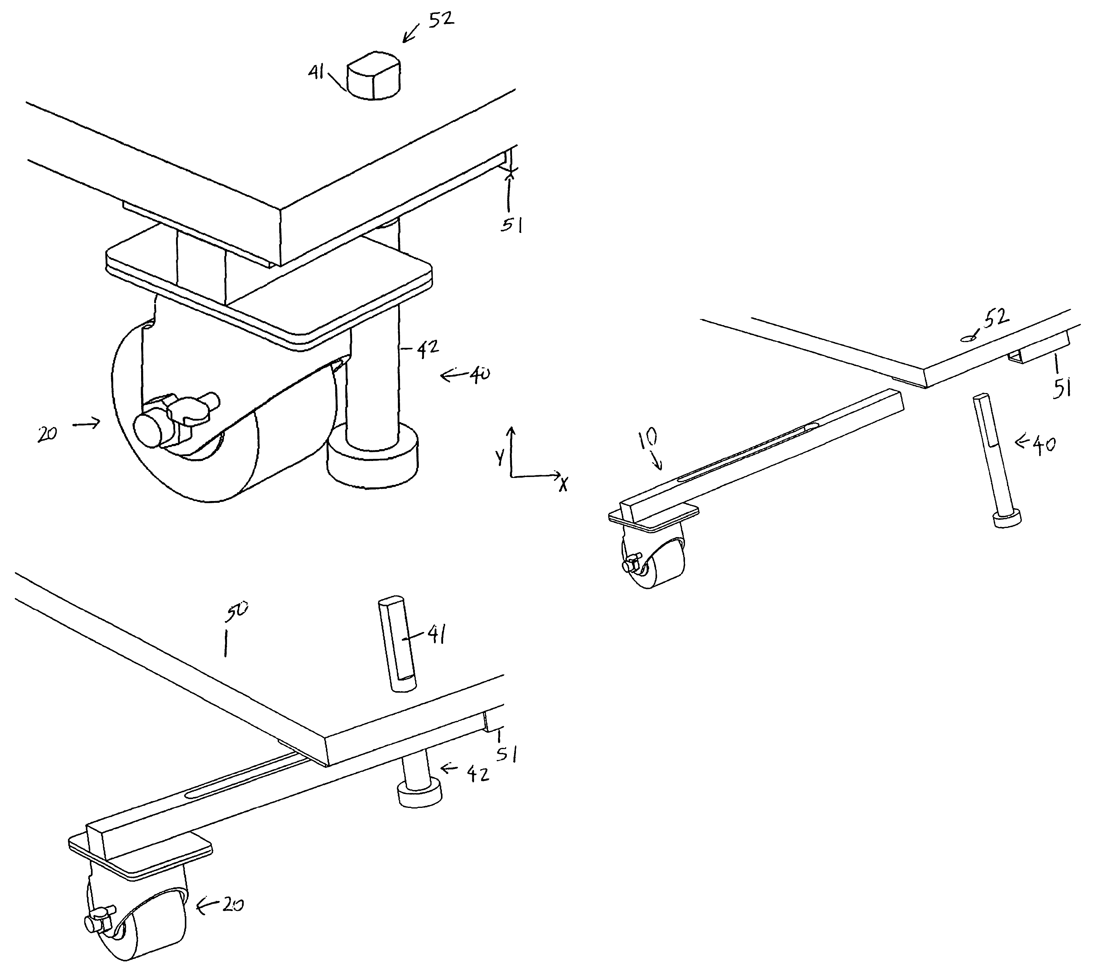
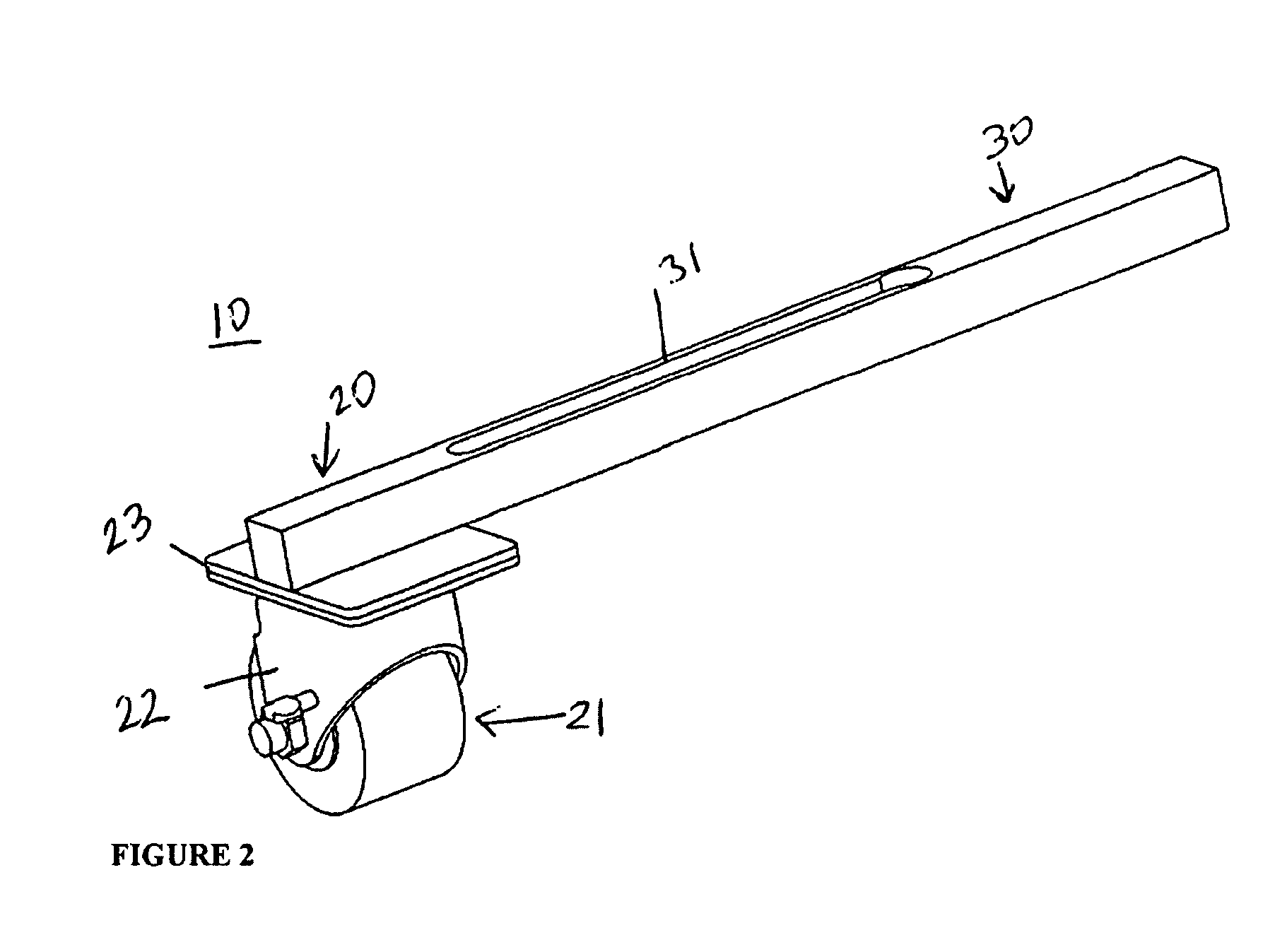
[0018]Referring to FIG. 2, the caster assembly 10 of the present invention is shown. The caster assembly 10 is comprised of a wheel assembly 20 and a horizontal orientated arm 30. The material of the arm is determined by the load each caster assembly will need to withstand. The length of the arm 30 is to be determined by the dimensions and weight of any given rack. The wheel assembly includes a wheel 21, wheel bracket 22, and a wheel plate 23. The wheel bracket 22 acts as a cover and secures the wheel 21. The horizontal orientated arm 30 extends along the x-axis relative to the wheel assembly 20, along a straight line path. The arm 30 is bolted to the wheel plate 23, however, alternate attachment methods known in the art are feasible. The arm 30 has slot 31 in the form of a keyhole slot. The rounded section of the keyhole slot 31 is a clearance hole for the leveling foot shaft 40, shown in FIG. 3. The slot 31 extends along the top portion of the arm 30 in a horizontal and linear dir...


PUM


Abstract

A novel caster assembly with a horizontally orientated arm is attached to a base plate of a rack during a travel state and a stored state. A leveling foot with a flat portion and a non-flat portion is inserted through a slot on the arm and a hole on the base plate such that during the travel state, the horizontal orientated arm is in a fully extended position, and during the stored state, the horizontal orientated arm is in a non- extended position.

Description

FIELD OF THE INVENTION[0001]The present invention generally relates to caster assemblies and in particular, extension caster assemblies for use with information technology server racks.BACKGROUND OF THE INVENTION[0002]Computer server products and their associated devices normally occupy enclosures that are referred to as racks. Racks provide space for housing equipment such as computer servers and other types of equipment. Racks are required to meet certain tip test standards. These standards provide guidelines that each rack must comply with for its most extreme allowable server configuration. Drawer density may be defined by the configuration of various server products within a rack, along with the sheer density of components and hardware comprising each server. As drawer density increases and new configurations are offered, it becomes increasingly challenging to populate racks and still pass testing.[0003]Increasing the foot print of a rack by add on extensions such as bolt on ca...

Claims


Application Information

Patent Timeline
Patent Type & Authority Patents(United States)
IPC IPC(8): B62B3/02
CPCB60B33/0002B60B33/0005B60B33/0015B60B33/0039B60B33/0049B60B33/0089B60B33/0026Y10T16/191
Inventor BORAAS, MICHAELHEGRENES, AARONKARL, NATHANLUND, DAVID
Owner LENOVO GLOBAL TECH INT LTD
Why Eureka
Try Eureka