Multi-pin light-emitting diode device

Inactive Publication Date: 2005-08-11
OPTO TECH
View PDF3 Cites 20 Cited by
  • Summary
  • Abstract
  • Description
  • Claims
  • Application Information

AI Technical Summary

Benefits of technology

[0007] For this purpose, how to design a novel light-emitting diode (LED) device, which may not only have the effect of preventing electrostatic damage, but also provid

Problems solved by technology

How to discharge heat, generated when irradiating, in order to keep the temperature of the light emitting die at an approximate working temperature becomes an important issue as the luminous emittance increases, because the increasing area of the light-emitting die or the larger working current supplied therefor has become a tendency for increasi

Method used


Image

  • Multi-pin light-emitting diode device
  • Multi-pin light-emitting diode device
  • Multi-pin light-emitting diode device

Examples


Embodiment Construction

[0019] The structural features and the effects to be achieved may further be understood and appreciated by reference to the presently preferred embodiments together with the detailed description.

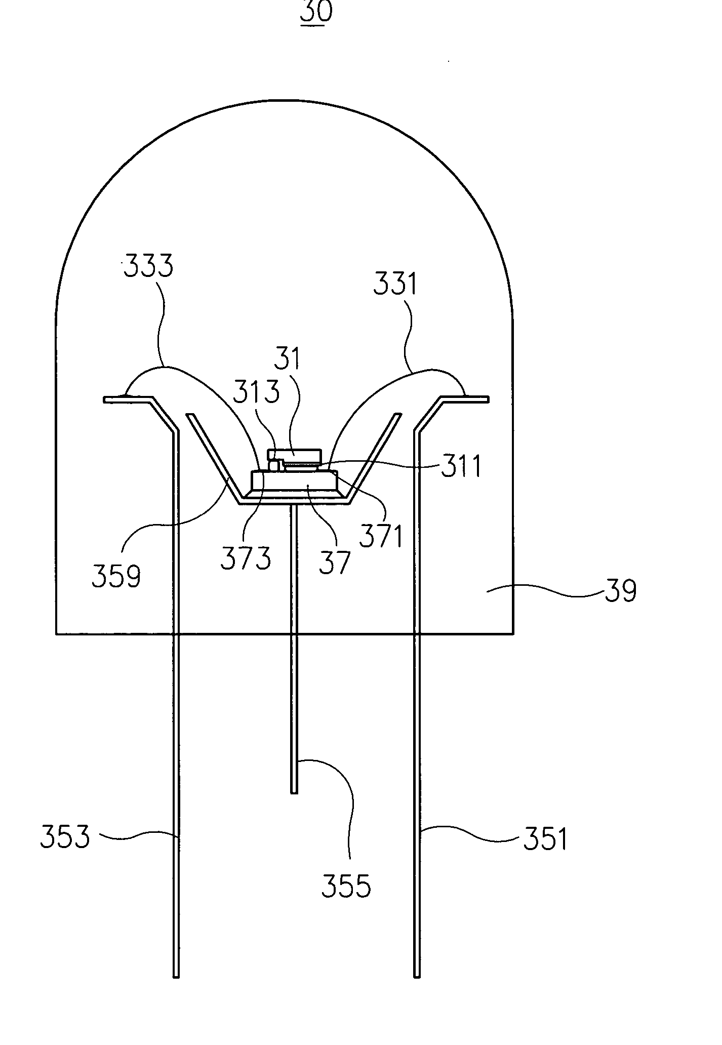
[0020] Referring to FIG. 3, firstly, there is shown a structural diagram according to one preferred embodiment of the present invention. The main structure of a light-emitting diode (LED) device 30, as shown in this figure, having high heat-dissipation efficiency and electrostatic protective effect, comprises at least one electrostatic discharge protection device 37, at least one light-emitting die 31, a first electro-conductive pin 351, a second electro-conductive pin 353, and at least one accommodating base 359.

[0021] The light-emitting die 31 includes a first electrode 311 and a second electrode 313, while the electrostatic discharge protection device 37 at least includes a first protective electrode 371 and a second protective electrode 373. For the light-emitting die 31, the flip-chip...


PUM


Abstract

A light-emitting diode (LED) device with at least three pins, mainly comprises an accommodating base provided therein with an electrostatic discharge protection device and at least one light-emitting die adhered onto this electrostatic discharge protection device in the manner of flip-chip, in such a way that a first electrode and a second electrode of the light-emitting die are electrically connected to a first protective electrode and a second protective electrode of the electrostatic discharge protection device, respectively and correspondingly. The accommodating base is connectedly provided with at least one heat-dissipating pin, and at the side of this accommodating base, a first electro-conductive pin and a second electro-conductive pin are provided, such that the first protective electrode and the second protective electrode are electrically connected thereto, respectively. As such, not only the function of prevention of electrostatic damage and high heat-dissipation efficiency may be provided, but also enhanced brightness of the LED device may be obtained.

Description

FIELD OF THE INVENTION [0001] The present invention is related to a light-emitting diode (LED) device, particularly to a LED device with at least three pins, having not only an electrostatic protective effect and high heat-dissipation efficiency, but also raised brightness thereof. BACKGROUND [0002] Owing to several advantages, such as small volume, low weight, low power consumption, and long service life, as examples, light-emitting diodes (LEDs) have been widely used in computer peripherals, communication products, and other electronic apparatuses. [0003] Referring to FIG. 1, there is shown a structural diagram of a conventional dual inline package (DIP) LED device. A LED device 10, as shown in this figure, is mainly provided with a light-emitting die 11 fixed in a pyramid portion 159 of a first lead frame 151. At the side of the first lead frame 151, there is provided with a corresponding second lead frame 153. For the light-emitting die 11, a first electrode 111 and a second ele...

Claims


Application Information

Patent Timeline
IPC IPC(8): H01L23/60H01L25/16H01L27/15H01L33/62H01L33/64
CPCH01L25/167H01L33/62H01L33/642H01L2224/32245H01L2224/48137H01L2924/12032H01L2224/48257H01L2224/49107H01L2224/73265H01L2224/48247H01L2224/48091H01L2924/00014H01L2924/00H01L2924/00012
Inventor LIN, MING-DERLIN, SAN BAO
Owner OPTO TECH
Why Eureka
Try Eureka