Connector provided with cover

a technology of connecting rods and covers, applied in the direction of coupling protective earth/shielding arrangements, coupling device connections, coupling bases/cases, etc., can solve the problems of contact and other electrostatic damage, and achieve the effect of eliminating the above electrostatic damag

Inactive Publication Date: 2006-10-24
MITSUMI ELECTRIC CO LTD
View PDF11 Cites 8 Cited by
  • Summary
  • Abstract
  • Description
  • Claims
  • Application Information

AI Technical Summary

Benefits of technology

[0005]It is therefore an object of the invention to provide a connector provided with a cover which is capable of eliminates the above electrostatic damage.
[0012]With the above configuration, electrostatic damage of the contact is prevented by the shield member.
[0014]In this case, the shield member can be easily and securely attached to the cover by the engagement members.

Problems solved by technology

In this connector, however, there is a probability that static electricity developed upon contact of the mating plug or other object with the shutter, so that the contacts and others were subjected to electrostatic damage.

Method used


Image

  • Connector provided with cover
  • Connector provided with cover
  • Connector provided with cover

Examples


Embodiment Construction

[0029]One preferred embodiment of the present invention will be described below in detail with reference to the accompanying drawings.

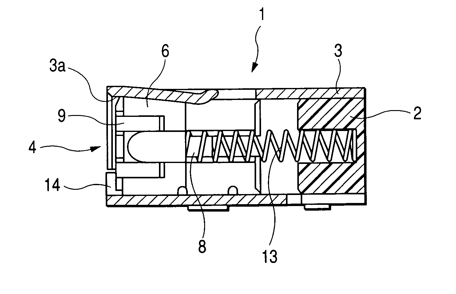
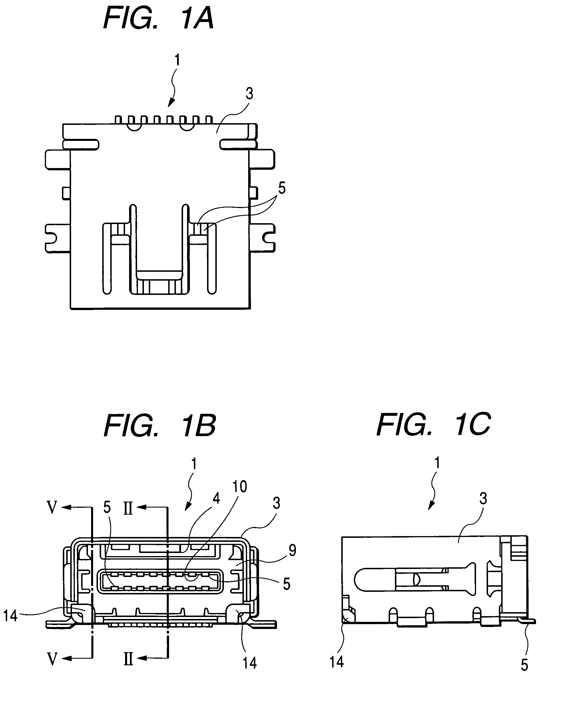
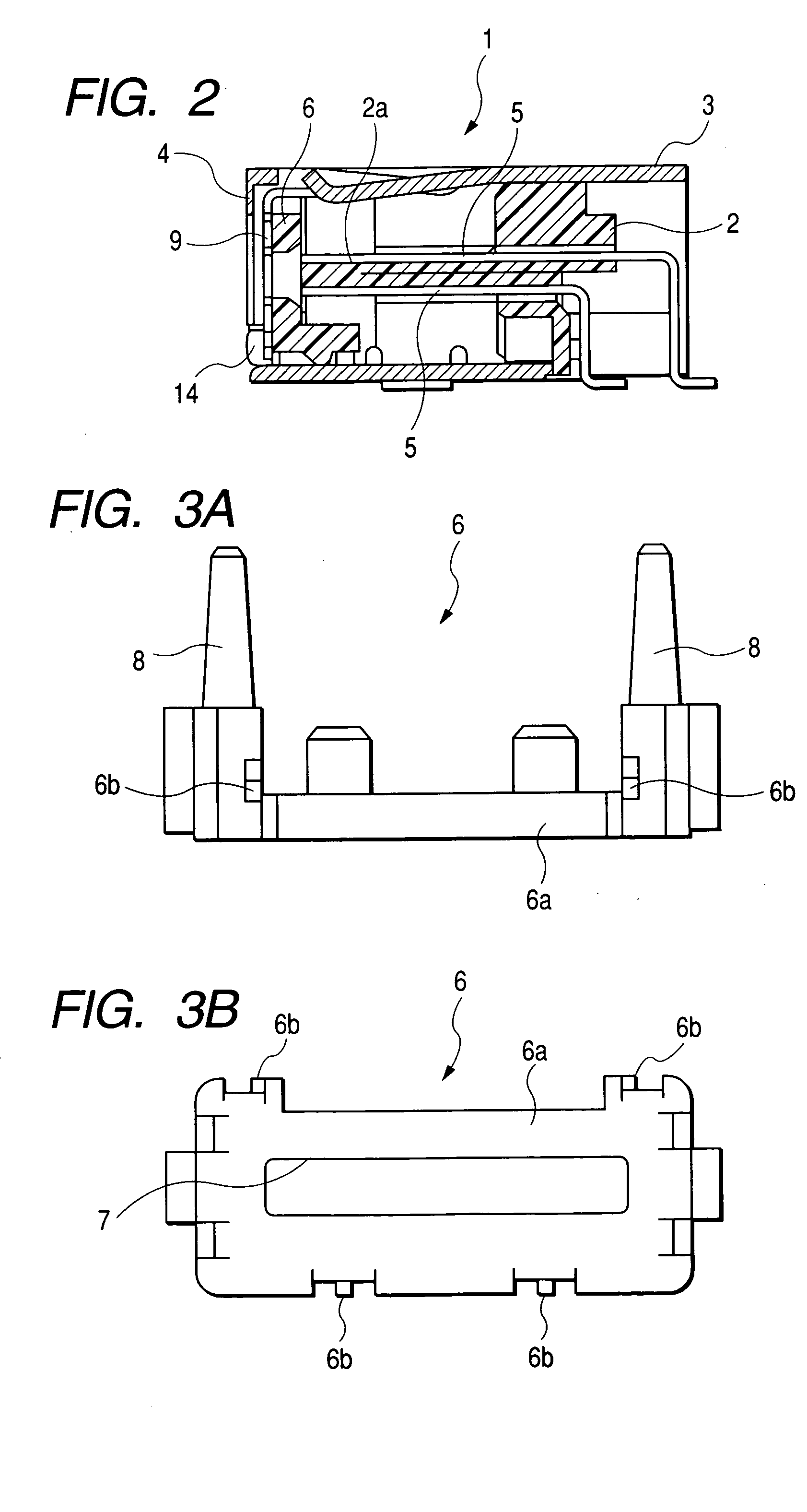
[0030]A connector 1 is used for charging a device such as a magneto-optic storage device or a video camera. The connector 1 includes a connector body 2 having a projecting portion 2a formed at a central portion of a front side (left side in FIG. 2) thereof. As shown in FIGS. 1A to 1C, an outer face of the connector body 2 is covered with a shield case 3 which is in the form of a square tubular assembly. As shown in FIG. 2, the shield case 3 extends forwardly beyond a front face the connector body 2 so as to define a fitting hole 4. Contacts 5 are arrayed upper and lower faces of the projecting portion 2a of the connector body 2, so that these contacts 5 are disposed at a central portion of the fitting hole 4 as shown in FIG. 1B.

[0031]A cover 6 for shielding or covering the contacts 5 at the front side thereof is slidably provided in the fitting hole 4...


PUM


Abstract

An insulative connector body is accommodated in a conductive shield case. A conductive contact is provided on the connector body. An insulative cover is accommodated in the shield case so as to be slidable between a first position for concealing the contact and a second position for exposing a part of the contact and allowing a mating connector to electrically contact therewith. A conductive shield member is attached onto a front face of the cover which faces the mating connector.

Description

BACKGROUND OF THE INVENTION[0001]This invention relates to a connector provided with a cover. More particularly, the invention relates to a connector in which contacts provided in a central portion of a connector body is shielded by a cover, and the shielding of the contacts by the cover is canceled in accordance with a connecting operation of the connector with respect to a mating plug, so that the contacts are prevented from electrostatic damage.[0002]Various connectors of this kind are already known, and for example, Japanese Patent Publication No. 2002-117931A (cf., pages 1 to 7, and FIGS. 1 through 6) discloses a connector provided with a shutter which is opened in accordance with an operation of connection of a connector body (socket) to a mating plug. This connector is provided with a lock cover which locks the shutter against sliding movement to an open position when the shutter is closed. In accordance with the operation of connection of the socket to the mating plug, this ...

Claims


Application Information

Patent Timeline
Patent Type & Authority Patents(United States)
IPC IPC(8): H01R13/44H01R13/648H01R13/453H01R13/52
CPCH01R13/4538
Inventor OHTA, YOSHINORIKONNO, TAKESHINAITO, SHINGO
Owner MITSUMI ELECTRIC CO LTD
Why Eureka
Try Eureka