
Attaching Device for End of Spring

a technology for fixing devices and end springs, which is applied in the direction of rod connections, manufacturing tools, chairs, etc., can solve the problems of increasing the cost of retainers and producing noise, and achieve the effect of preventing noise from being generated

Inactive Publication Date: 2011-02-24
TS TECH CO LTD
View PDF8 Cites 9 Cited by
  • Summary
  • Abstract
  • Description
  • Claims
  • Application Information

AI Technical Summary

Benefits of technology

[0005]It is therefore an object of the present invention to provide an attaching device for fixing end portions of springs to a round shaft, which can overcome the foregoing problem associated with a diameter of the round shaft to which the attaching device is applied, is inexpensive, and can prevent noise from being generated due to rubbing of the attaching device with the round shaft.
[0006]It is another object of the present invention to provide an attaching device for fixing end portions of springs to a round shaft, which can cause the end portions of the springs to be stably fixed to the round shaft and can be applied to the round shaft with simple operation.
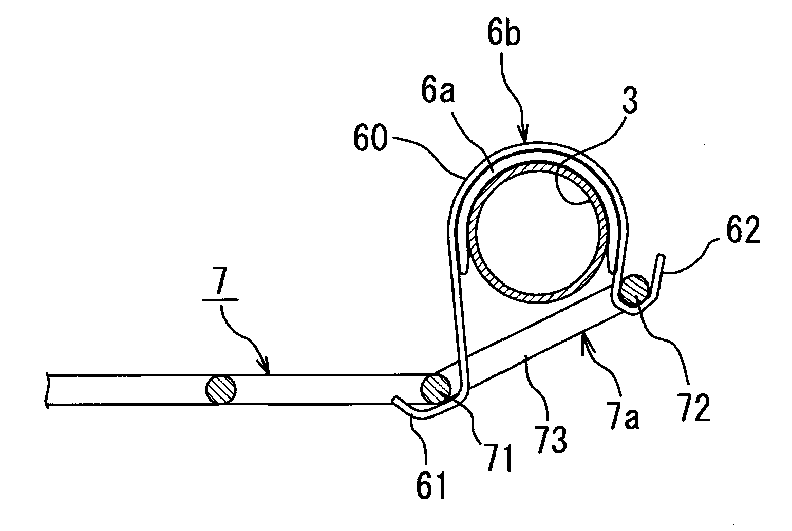
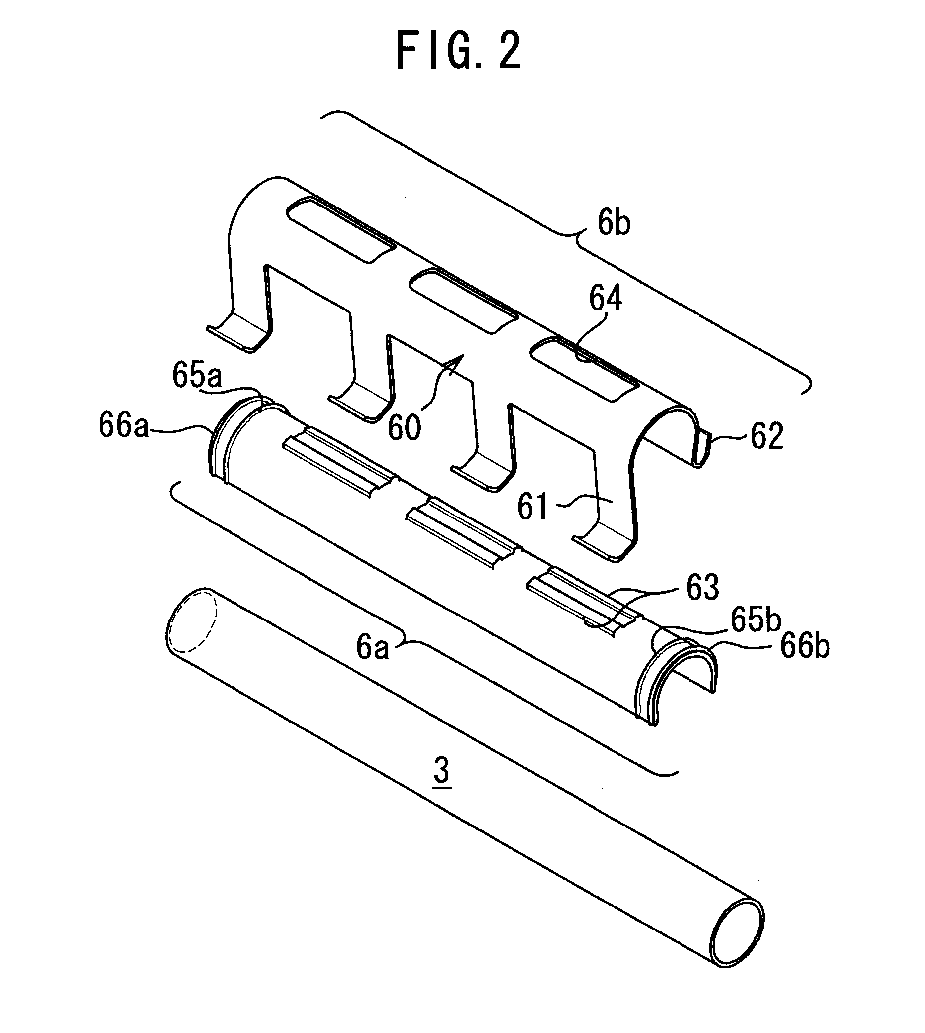
[0008]The attaching device of the present invention which is constructed as discussed above comprises the resin-made collar having a substantially U-shape in cross-section and adapted to be fitted over the round shaft, and the metal-made retainer adapted to be fitted over the resin-made collar on the round shaft, so that even if there is a size difference between an outer circumference of the round shaft and an inner circumference of the resin-made collar, such a size difference can be easily cancelled by elastic deformation of the resin-made collar. More particularly, in a case where the attaching device is applied to a round shaft having a diameter slightly larger than the inner circumference of the collar, fitting of the collar over the round shaft can be easily performed while causing the collar to be deformed in such a manner that an opening of the collar is operatively widened. Even if the attaching device is applied to a round shaft having a diameter smaller than the inner circumference of the collar and a clearance between the round shaft and the collar is produced, production of noise between the attaching device and the round shaft can be effectively prevented by the resin-made collar. Therefore, in order to prevent the production of the noise, application of a resin coating or the like onto the attaching device is not required, thus resulting in reduced cost of the attaching device.
[0010]In a preferred embodiment according to the present invention, a plurality of springs may be stretched between the opposing frame sections so as to be spaced apart from one another, and the collar and the body of the retainer may be formed longitudinally, the longitudinal body of the retainer having pairs of first and second spring engagement pieces provided at both edges of the longitudinal body, and the pairs of first and second spring engagement pieces corresponding in number to the springs. In this case, the collar which is adapted to be fitted over the round shaft is formed longitudinally and the retainer which includes the longitudinal body and the pairs of first and second spring engagement pieces provided at the both edges of the longitudinal body, so that end portions of the plurality of springs can be easily fixed to the single round shaft by the attaching device.
[0011]In a preferred embodiment according to the present invention, the collar may have at least one elongated-protrusion rising up from a top surface thereof, and the body of the retainer may have at least one through-hole that is formed in a top surface of the body and adapted to be engagedly fitted over the at least one elongated-protrusion when the body of the retainer is mounted on the collar on the round shaft. In this case, the retainer can be prevented from being rotated or circumferentially shifted relative to the collar.

Problems solved by technology

Moreover, when the retainer which is formed of metal material is directly fitted over the metal-made round shaft, there is a possibility that noise will be produced by rubbing the metal-made retainer with the metal-made round shaft.
In order to prevent the production of the noise, application of a resin coating onto the retainer is required, thus resulting in increased cost of the retainer.

Method used


Image

  • Attaching Device for End of Spring
  • Attaching Device for End of Spring
  • Attaching Device for End of Spring

Examples


Embodiment Construction

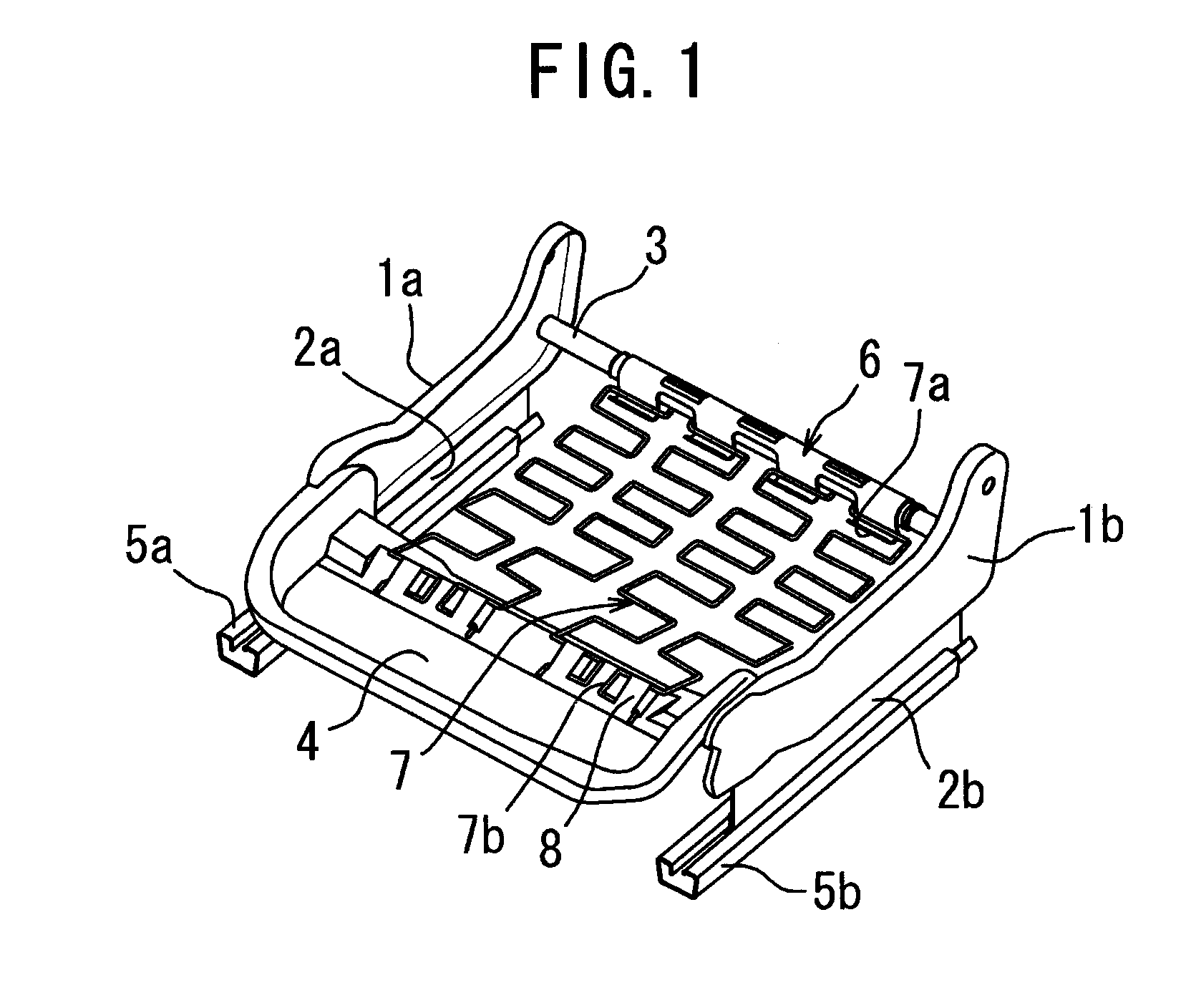
[0021]Referring to FIG. 1, there is illustrated a seat cushion frame for a slide-type vehicle seat, in which springs are employed as means to support a cushion for a seat cushion of the vehicle seat and fixed at end portions thereof to the seat cushion frame by an attaching device 6 for fixing end portions of springs according to an embodiment of the present invention. The seat cushion frame comprises a pair of spaced apart left and right side frame sections 1a, 1b, a pair of spaced apart upper rail members 2a, 2b integrally attached to the side frame sections 1a, 1b, a round shaft 3 formed from a round pipe or round rod, the round shaft 3 being attached between rear end portions of the side frame sections 1a, 1b, and a pan frame member 4 attached between forward end portions of the side frame sections 1a, 1b. In FIG. 1, reference numerals 5a, 5b denote lower rail members to which the upper rail members 2a, 2b are slidably supported.

[0022]In the seat cushion frame, a plurality of sp...


PUM


Abstract

There is disclosed an attaching device (6) for fixing an end portion (7a) of at least one spring (7) for supporting a cushion for a seat, to a seat frame of the seat, wherein the seat frame includes opposing seat frame sections, one of the opposing seat frame sections being formed from a round shaft (3), the at least one spring being stretched between the opposing seat frame sections, and the end portion of the at least one spring being formed substantially in a U-shape in outline. The attaching device (6) comprises a resin-made collar (6a) of a substantially reverse U-shape in cross-section adapted to be fitted over the round shaft (3) and a metal-made retainer (6b) including a body (60) having a geometry of similar figure with the collar and adapted to be fitted over the collar on the round shaft, and at least one pair of inner and outer spring engagement pieces (61, 62) provided at both edges of the body, the inner and outer spring engagement piece extending downward from the both edges of the body and bent laterally outwardly at lower ends thereof. A first axial region (71) and second axial region (72) of the substantially U-shaped end portion (7a) of the at least one spring (7) are adapted to be engaged with the inner spring engagement piece (61) and the outer spring engagement piece (62), respectively, whereby the end portion of the at least one spring is adapted to be fixed to the round shaft through the attaching device.

Description

TECHNICAL FIELD[0001]The present invention relates to an attaching device for fixing end portions of springs to be stretched between opposing frame sections of a seat cushion frame for a seat and, more particularly, to an attaching device for fixing end portions of springs, each of which has a substantially U-shape in outline, to a round shaft which is employed as a frame section constituting one of opposing frame sections of a seat cushion frame for a seat.BACKGROUND ART[0002]As a vehicle seat, there has been proposed a vehicle seat in which a metal-made round shaft is employed as a rear frame section of a seat cushion frame for the seat, zigzag springs for supporting a cushion thereon are stretched between the round shaft and a forward frame section of the seat cushion frame, and end portions of the zigzag springs are fixed to the round shaft by a retainer (Japanese Patent Application Laid-Open No. 2006-14867).[0003]The retainer comprises a longitudinal body of a substantially U-s...

Claims


Application Information

Patent Timeline
IPC IPC(8): F16B7/08
CPCB60N2/7041B60N2/72A47C7/285F16B2/22Y10T24/44701Y10T403/4614Y10T24/4406Y10T403/7176B60N2/7094F16B2/241
Inventor KOTAKI, TOMONORI
Owner TS TECH CO LTD
Learn More