
Method for the fabrication of a screw member for plate member fastener

Inactive Publication Date: 2011-02-24
WANG KUO CHUNG
View PDF3 Cites 8 Cited by
  • Summary
  • Abstract
  • Description
  • Claims
  • Application Information

AI Technical Summary

Benefits of technology

[0009]The present invention has been accomplished under the circumstances in view. It is therefore the main object of the present invention to provide a method for the fabrication of a screw member for plate member fastener, which facilitates mounting and dismounting of the plate member fastener, avoiding overthreading during installation.
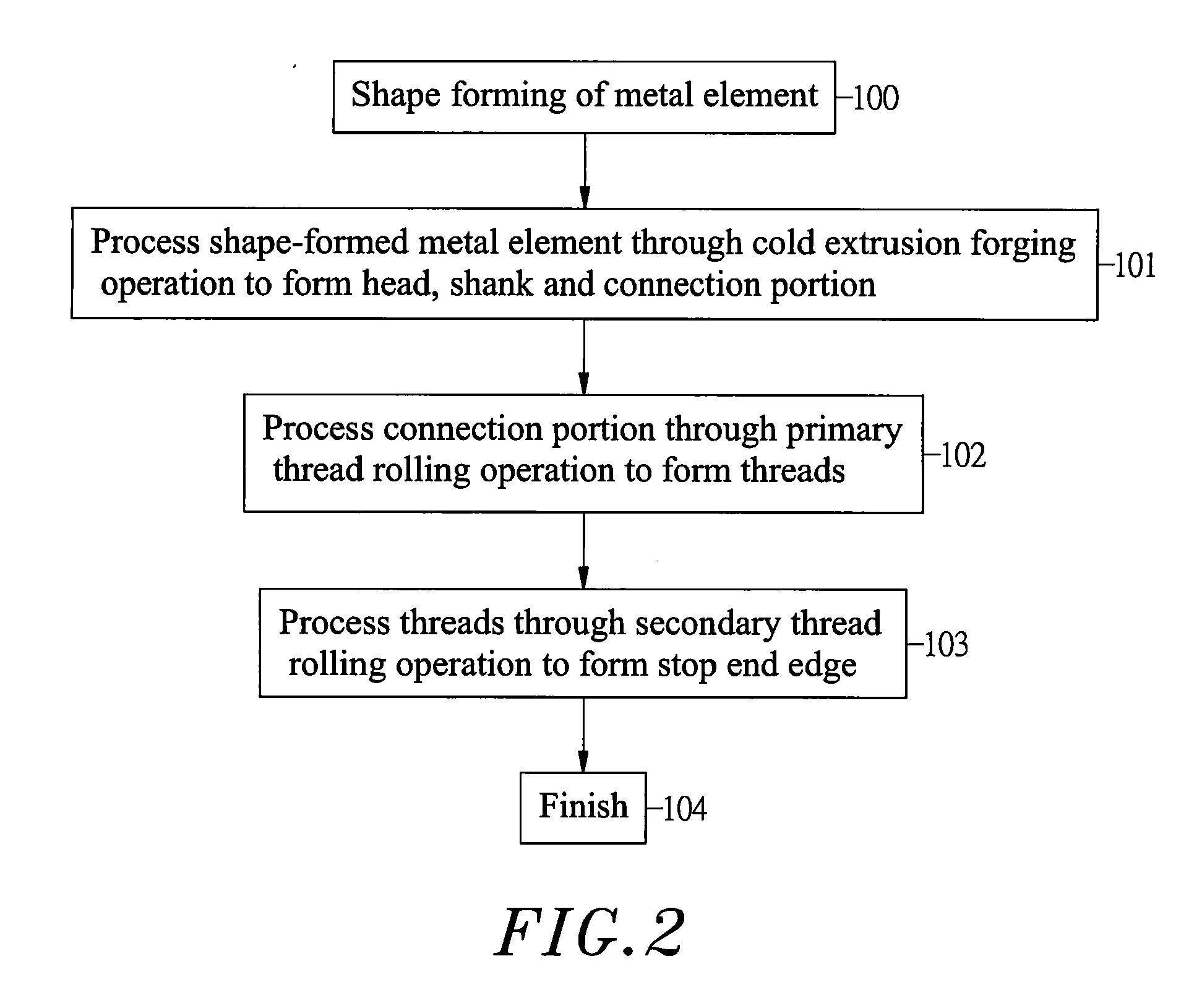
[0010]A screw member fabrication method in accordance with the present invention includes the steps of (a) preparing a metal element subject to a predetermined size, and then processing the metal element through a cold extrusion forging operation to form a head at one end, a connection portion at an opposite end and a shank between said head and said connection portion, (b) processing the connection portion through a thread rolling operation to form threads around the periphery of the connection portion, (c) processing threads to form a stop end edge at one side in proximity to the shank, and (d) finishing the final product. When the screw member is used in a plate member fastener and threaded through a mounting through hole on a first metal plate member into a corresponding screw hole of a second metal plate member to secure the first metal plate member and the second metal plate member together, the stop end edge of the screw member avoids overthreading, preventing sticking of the screw member in the second metal plate member.
[0011]Further, the stop end edge is a flat edge extending in direction perpendicular to the axis of the screw member. When the screw member is used in a plate member fastener and a spring member is sleeved onto the screw member and stopped between the bottom side of the head and stop end edge of the screw member, the screw member will not be forced to bias and can be accurately threaded into the screw hole of the second metal plate member.

Problems solved by technology

When the screw member A, the cap and the locating base are assembled, the cap and the locating base may be not kept in perfect alignment.
Small deviation of the component parts may increase the difficulty of the installation of the plate member fastener.

Method used


Image

  • Method for the fabrication of a screw member for plate member fastener
  • Method for the fabrication of a screw member for plate member fastener
  • Method for the fabrication of a screw member for plate member fastener

Examples


Embodiment Construction

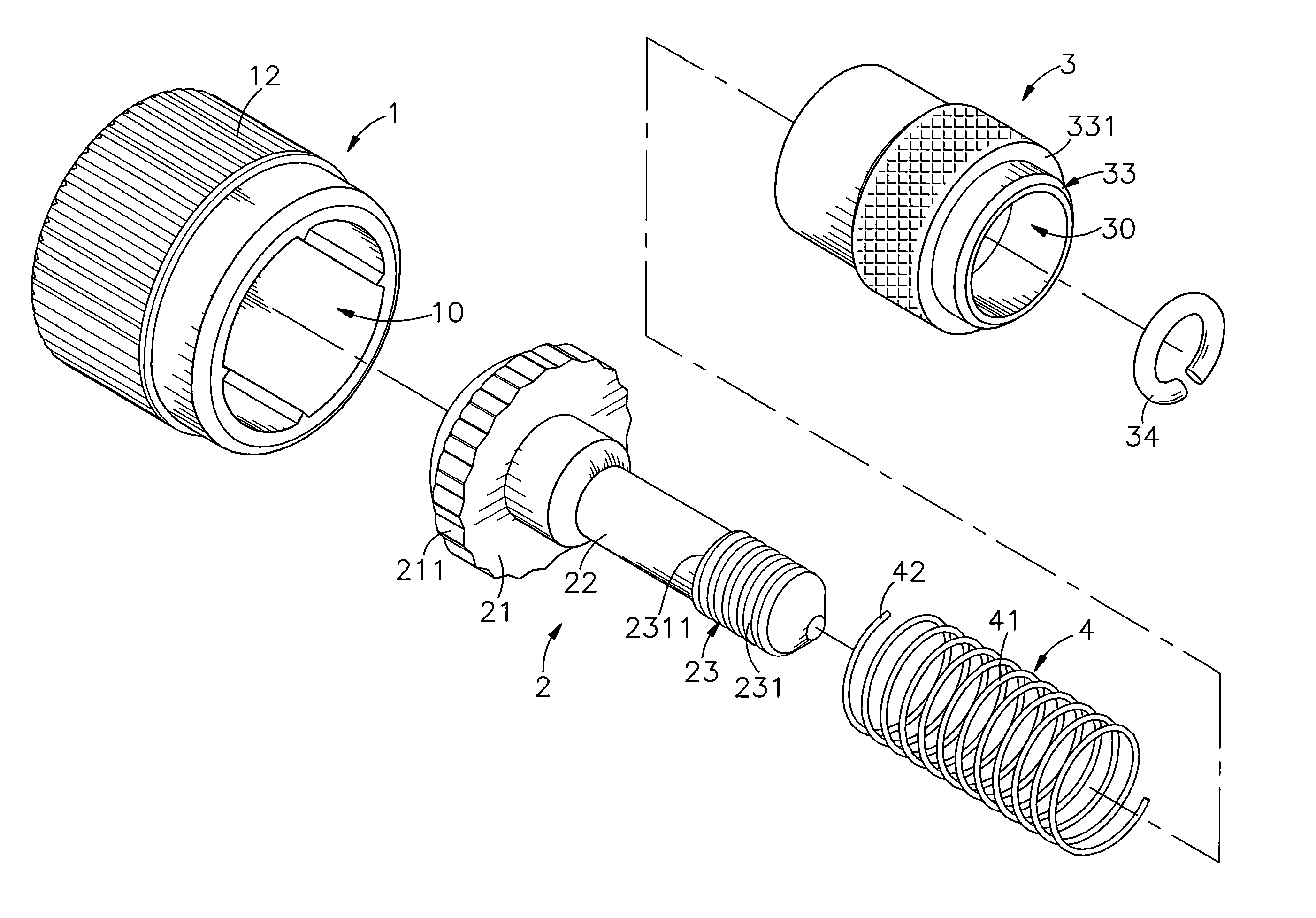
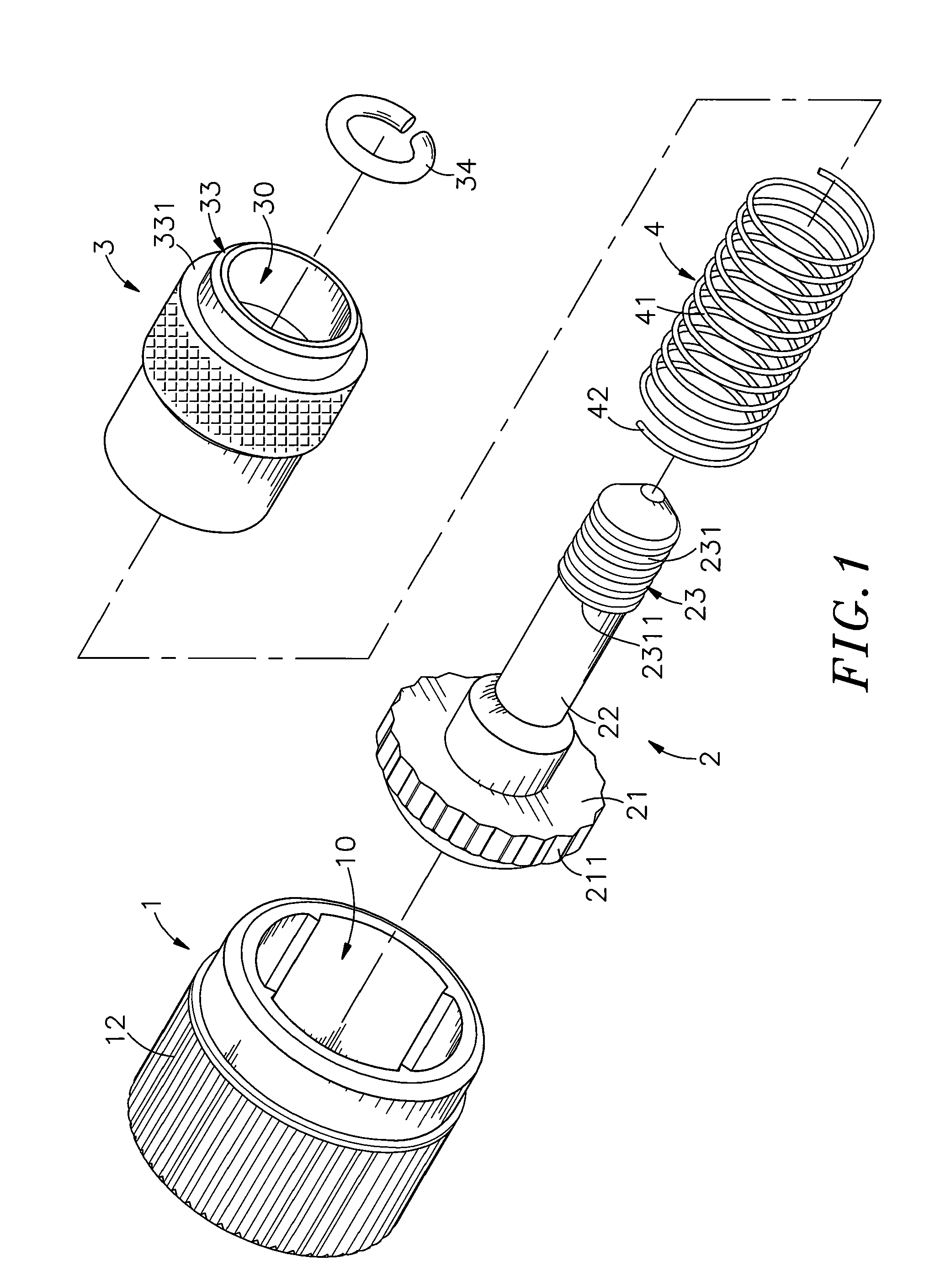
[0021]Referring to FIGS. 1 and 7, a plate member fastener in accordance with the present invention comprises a cap 1, a screw member 2, a barrel 3, and a spring member 4.

[0022]The cap 1 is a hollow member having a center opening 10 axially extending through the top and bottom sides for receiving the barrel 3, the screw member 2 and the spring member 4, a serrated inside retaining portion 11 arranged around the inside wall near the top side for retaining the engagement portion 211 of the screw member 2, and a grip 12 located on the periphery at the top side for gripping by hand.

[0023]The screw member 2 is a metal member having a head 21, an engagement portion 211 formed on the periphery of the head 21 for engagement with the serrated inside retaining portion 11 of the cap 1, a shank 22 perpendicularly extended from the center of the bottom wall of the head 21 and terminating in a connection tip 23, threads 231 spirally arranged around the periphery of the connection tip 23 and defini...


PUM

PropertyMeasurementUnit
Sizeaaaaaaaaaa
Proximity effectaaaaaaaaaa

Abstract

A method for making a screw member for plate member fastener is disclosed to include the step of preparing a metal element subject to a predetermined size and then processing the metal element through a cold extrusion forging operation to form a head at one end, a connection portion at an opposite end and a shank between the head and the connection portion, the step of processing the connection portion through a thread rolling operation to form threads around the periphery, the step of processing the threads to form a stop end edge at one side in proximity to the shank, and the step of finishing the final product.

Description

BACKGROUND OF THE INVENTION[0001]1. Field of the Invention:[0002]The present invention relates to a plate member fastener fabrication method and more particularly, to a method for making a screw member for plate member fastener that raises reliability of the use of the plate member fastener.[0003]2. Description of the Related Art:[0004]When fastening plate members together, a positioning screw formed of a knob, a ring and a screw nail is usually used. During installation, the screw nail and the ring are secured to the first plate member, and then the knob is rotated to drive the screw nail into the second plate member, and then a hand tool is used to fasten tight the screw nail, affixing the first and second plate members together. This plate member joining method can be used in a machine tool to join plate members together.[0005]The power drive or speed-adjustment unit of a machine tool is provided inside the housing. To facilitate repair of the machine tool or adjustment of the ou...

Claims


Application Information

Patent Timeline
IPC IPC(8): B21K1/56
CPCB21H3/06B21K1/56B21K1/46
Inventor WANG, KUO-CHUNG
Owner WANG KUO CHUNG
Learn More