Method and device for the treatment of glaucoma

a glaucoma and treatment method technology, applied in the field of glaucoma treatment methods and devices, can solve the problems of most temporary effects, and achieve the effect of reliable natural regulation of eye inner pressur

Inactive Publication Date: 2011-02-24
GRIESHABER OPHTHALMIC RES FOUND
View PDF9 Cites 109 Cited by
  • Summary
  • Abstract
  • Description
  • Claims
  • Application Information

AI Technical Summary

Benefits of technology

[0011]The present invention resolves prior art problems by providing natural drainage of the aqueous humor of an eye suffering form glaucoma and to restore and permanently maintain it in the foregoing manner such that the aqueous humor drains from the anterior chamber via the trabecular tissue into the Sc...

Problems solved by technology

These techniques in the prior art have however the d...

Method used


Image

  • Method and device for the treatment of glaucoma
  • Method and device for the treatment of glaucoma
  • Method and device for the treatment of glaucoma

Examples


first embodiment

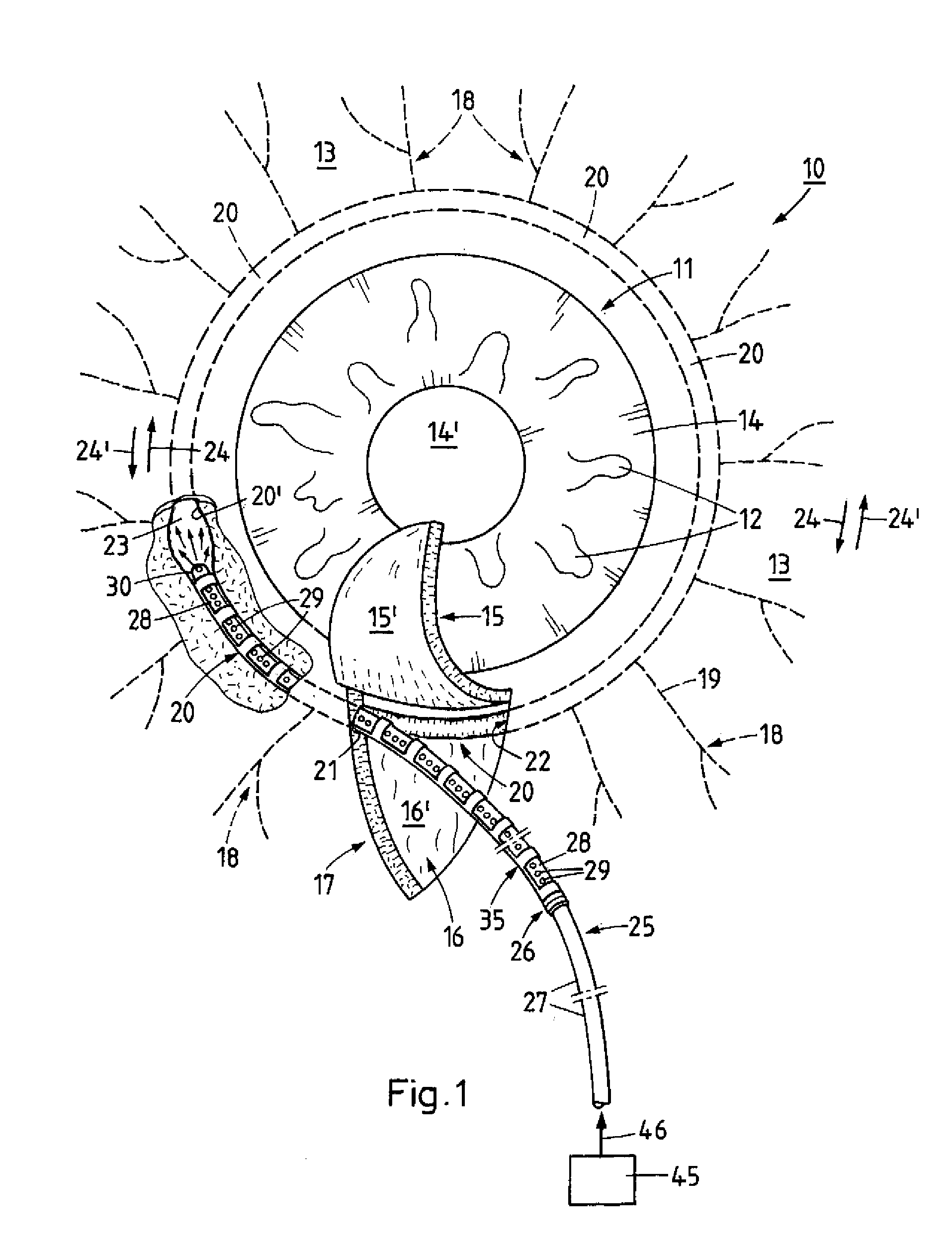
[0039]FIG. 3 shows the implant 35 made from an elongated flexible tube 36. The implant 35 is of a configuration that includes a connecting part 35b continuously extending in axial direction along a longitudinal axis Z with a substantially circular-shaped cross sectional profile, and disposed thereon several ring members 35c spaced apart by recesses 35a. The circular interior space 35e of the connecting part 35b flanked by the ring members 35c, is constructed for receiving the tube-shaped distal portion 28 of the catheter 25.

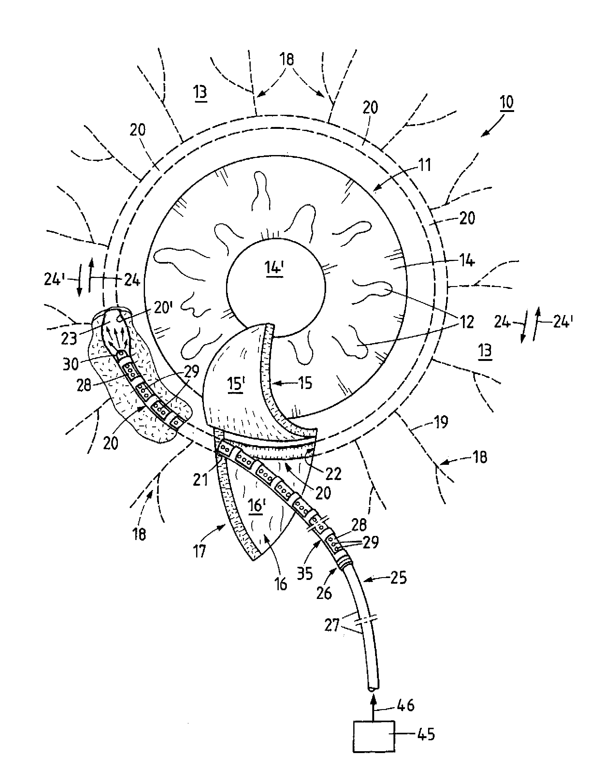
[0040]The length L of the implant 35 corresponds either to the location of the afflicted site or corresponds to a distance extending from the first opening 21 to the second opening 22 of the circumference of the Schlemm's canal 20. The circular Schlemm's canal 20 has a diameter approximately from 10.0 mm to 12.0 mm which is preferably determined prior to the surgical procedure for the respective eye 10, and computed in dependence on the entire extension of the le...

second embodiment

[0042]FIG. 5 shows an example of an implant 35 made form a flexible elongated tube 36 and in the direction of longitudinal axis Z, two diametrically opposed connection parts 35b as well as several ring members 35c in direction of the longitudinal axis Z and distanced from each other by recesses 35a. The recesses 35a each respectively connect to the interior 35e and are configured in rectangular shape in this embodiment. However, the recesses 35a can also be of an oval, elliptical, square or trapezoidal shape. The length L of the implant 35 according to FIG. 5 is computed analog implant 35 as described in connection with FIG. 3.

[0043]FIG. 6 shows the cross section of the profile of the circular ring-shaped implant 35 according to the section line B-B in FIG. 5, where the two connecting parts 35b are shown disposed diametrically opposite relative to each other and in direction of the longitudinal axis. In one of the connecting parts 35b, the slot-shaped gap 35d oriented in direction o...

third embodiment

[0056]FIG. 12 shows a top view of the implant 35 made from the elongated flexible tube 36. The implant 35 includes the connection part 35b which extends along the longitudinal axis Z and has a substantially circular cross section, as well as the ring parts 35c that are spaced apart by the recesses 35a. The connection part 35b and the ring parts 35c having interior space 35e are constructed for receiving the tube-shaped distal portion 28 of catheter 25 (FIG. 9).

[0057]The ring parts 35c which are spaced apart by recesses 35a and disposed at tube 36 maybe also, as schematically illustrated in FIG. 12, disposed in grouped and in axial disposition of two or more ring parts 35c at any location at the implant 35.

[0058]In a variant to the first embodiment (FIG. 3) of implant 35, the ring parts 35c in the embodiment according to FIG. 12 are formed by a first ring member 35c′ and a second ring member 35c″ which meet at a Z-shaped gap. The approximately semi-circular shaped ring members 35c′ a...


PUM


Abstract

The invention relates to a method and device for the treatment of glaucoma, though insertion of an implant into the lumen of the Schlemm's canal to realize proper drainage of the aqueous humor, which implant is brought into its position in the Schlemm's canal by means of a catheter having a distal and a proximate portion and provided with a number of pores through which a gaseous or fluid medium which comes from a pressure source can emerge during insertion of the catheter carrying the implant into the Schlemm's canal, and while the catheter is being inserted into the Schlemm's canal the gaseous or fluid medium is released under pressure thereby expanding the Schlemm's canal and the implant and upon releasing the implant at its determined location, the catheter can be withdrawn from the Schlemm's canal.

Description

[0001]The present invention relates in general to a method and a device for the treatment of glaucoma, and more specifically to a method whereby a tube-shaped implant is introduced into Schlemm's canal which has been exposed through a scleral incision and the implant placed at a target location in the Schlemm's canal.BACKGROUND OF THE INVENTION[0002]In a healthy eye, the drainage of the circulating aqueous humor takes place in known manner, here not illustrated in detail, from the rear chamber to the front chamber and in the area of the irido-corneal angle (angulus irido-cornealis) drains via the trabecular meshwork into the lumen of the circular Schlemm's canal and from there reaches the blood stream via the episcleral vein system. In a pathological condition of the afflicted eye, and such obstructions as for example, a blocked Schlemm's canal, continuous drainage of the aqueous humor, which is generated by the epithelial layer of the ciliary body and renewed on an ongoing basis, i...

Claims


Application Information

Patent Timeline
IPC IPC(8): A61F9/00A61M27/00
CPCA61B2019/5437A61F9/00781A61F9/0017A61B2019/5441A61B2090/3937A61B2090/3941A61M25/01
Inventor STEGMANN, ROBERT CHRISTOPHERGRIESHABER, MATTHIAS CHRISTIANGRIESHABER, HANS RUDOLF
Owner GRIESHABER OPHTHALMIC RES FOUND
Why Eureka
Try Eureka