Chemical distribution system for floor cleaning machine

a technology for cleaning machines and chemicals, applied in carpet cleaners, instruments, photosensitive materials, etc., can solve the problems of ineffective and inefficient cleaning of floors of the and the above-described first type of scrubber is not optimized for dealing with various types and amounts of dirt and debris,

Inactive Publication Date: 2011-03-03
NSS ENTERPRISES INC
View PDF3 Cites 7 Cited by
  • Summary
  • Abstract
  • Description
  • Claims
  • Application Information

AI Technical Summary

Problems solved by technology

Further, the various floors and surfaces are subject to different kinds and amounts of debris and dirt.
Consequently, the above-described first type of scrubber is not optimized for dealing with various types of floors and various kinds and amounts of dirt and debris.
As a result, it has been found that this first type of scrubber is ineffective and inefficient at cleaning floors.
It has been found, however, that many times the operator's calculation for increasing or decreasing an overall cleaning chemical ratio of a cleaning solution in the onboard fluid tank is incorrect or is made too casually.
This results in wasted cleaning chemicals and an inefficient cleaning method.
There are numerous disadvantages associated with the current known designs for this second type of scrubber.
Since some cleaning circumstances call for increased or decreased fluid flow, this is a disadvantage.
Further, the chemical metering system makes it difficult to change a type of cleaning chemical and a rate at which the cleaning chemical is drawn from the separate chemical container.
These specially designed chemical containers add to the expense of the system and do not permit an operator to use chemical containers from other suppliers that may be less expensive and equally, if not more, effective.

Method used


Image

  • Chemical distribution system for floor cleaning machine
  • Chemical distribution system for floor cleaning machine
  • Chemical distribution system for floor cleaning machine

Examples


first embodiment

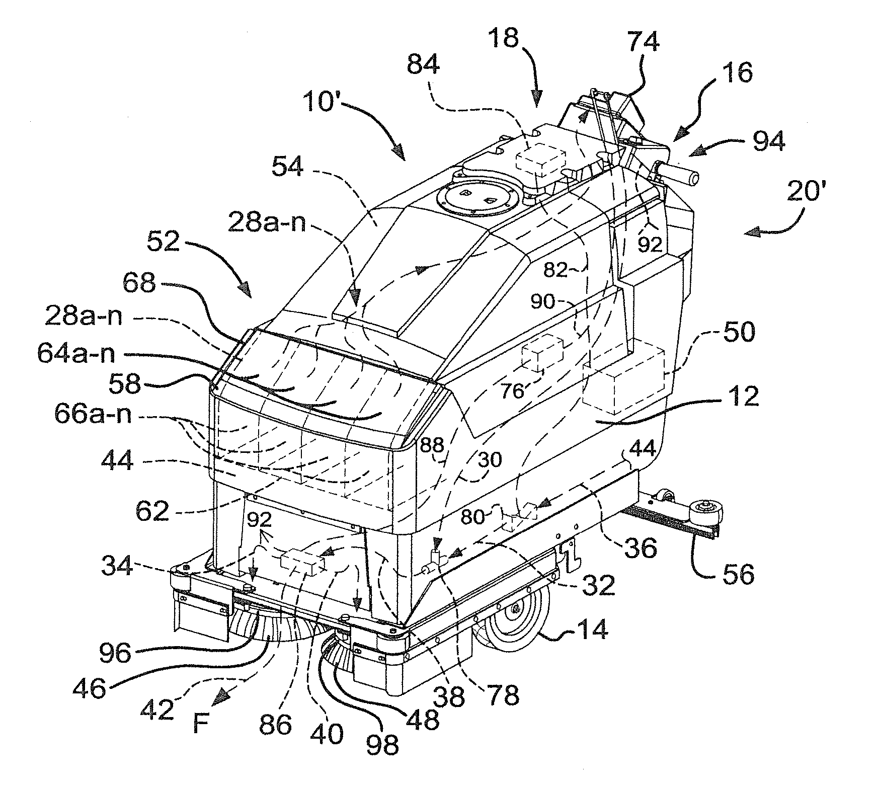
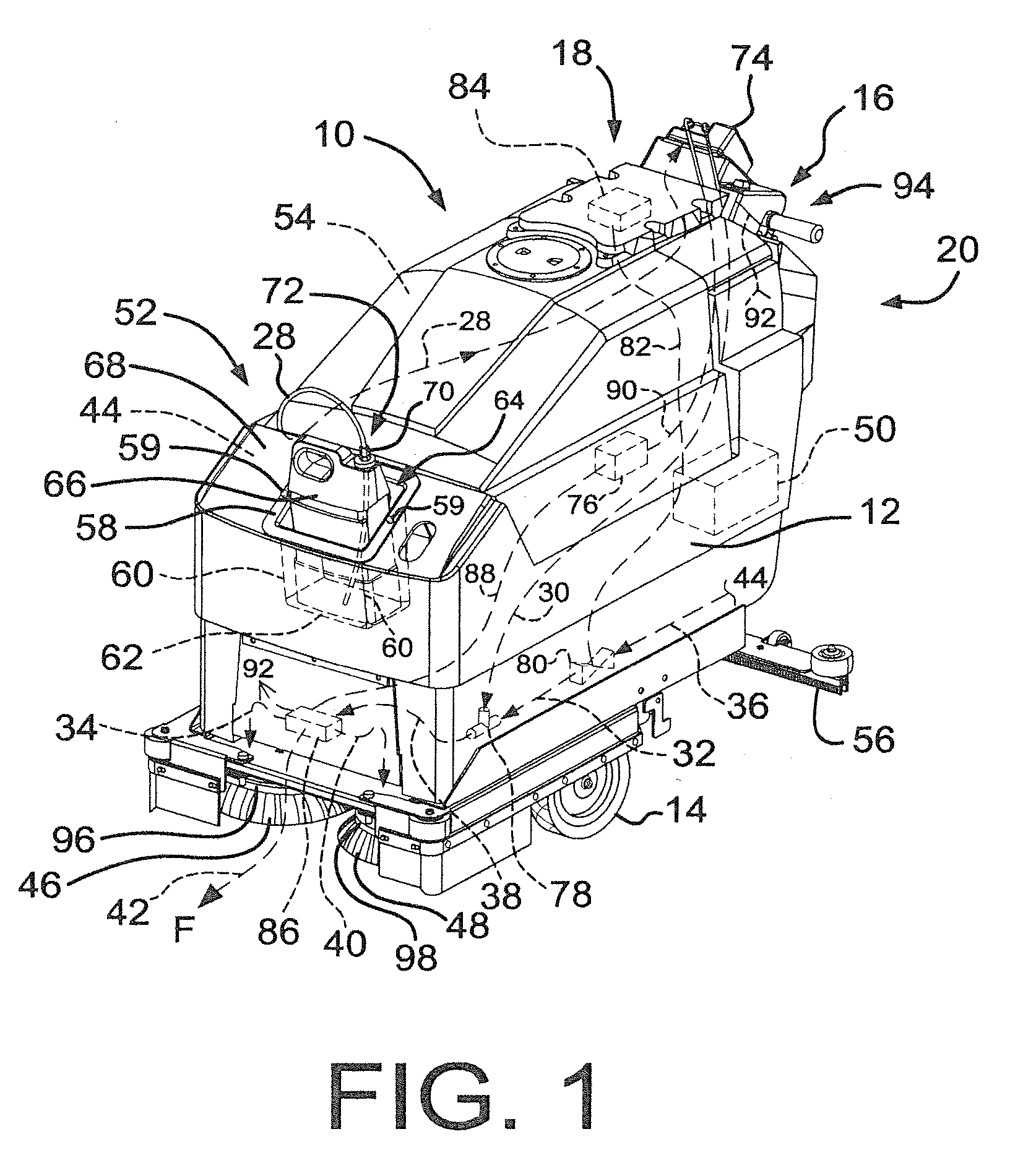
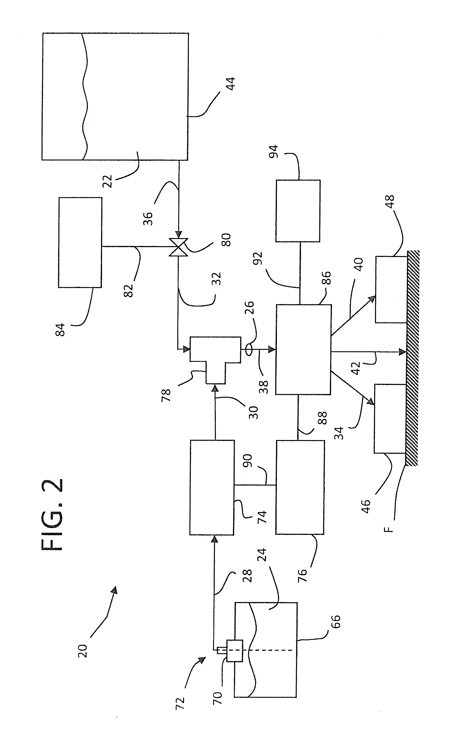
[0021]FIGS. 1 and 2 depict a floor cleaning machine 10, with a chemical distribution system 20, utilized with the present invention. The floor cleaning machine 10 of FIG. 1 is an automatic floor scrubber but the present invention is not limited to floor scrubbers. Instead, the present invention maybe used with any floor cleaning machine known to those skilled in the art.

[0022]The automatic floor scrubber 10 is constructed of a body portion 12 mounted on a set of wheels 14 (one or more not shown but common in the art) that permits the body portion 12 to be moved over a floor F. Machine controls 16 are provided for an operator to turn the machine 10 on and off, to steer and control the speed of the machine 10 and monitor machine performance, among other functions provided by automatic scrubbers in general. The machine controls 16 are provided at a rear portion 18 of the machine 10, where the operator is located.

[0023]In general, the flow of fluids 22, 24, 24a-n, 26, 26′ throughout FIG...

embodiment 10

[0030]FIG. 1 further depicts a container receptacle 58 in the forward portion 52 of the body portion 12. In the depicted embodiment 10, the container receptacle 58 is attached to or formed at least partially within the outer surface 68 of the scrubber 10. Therefore, a portion of the volume of the solution tank 44 is reduced approximately by the volume of the container receptacle 58. This is not problematic, however, because the volume of the solution tank 44 is large and the volume taken up by the container receptacle 58 is relatively small in comparison.

[0031]The container receptacle 58 may be a separate component that is attached to the body portion 12 or it may be integrally formed, one-piece and unitary with the body portion 12. In the depicted embodiment 10, the container receptacle 58 is a separate component that is attached to the body portion 12 with mechanical fasteners 59, like screws that are common in the art. Other means, in addition to or separately from mechanical fas...


PUM


Abstract

A chemical distribution system for a floor cleaning machine is described. The system utilizes at least one container that is selectively connected to a pump that pumps a cleaning chemical solution from the container into a tee for combining with a fluid from an onboard fluid tank at a rate determined by a machine operator. Chemical containers may be readily and interchangeably connected to the pump to permit various solutions to be selectively utilized to optimize floor cleaning.

Description

RELATED APPLICATIONS[0001]This application claims the benefit, under 35 U.S.C. §119(e), of U.S. Provisional Patent Application Ser. No. 61 / 275,621, filed Aug. 31, 2009, under 35 U.S.C. §111(b), which application is incorporated by reference herein in its entirety.FIELD OF THE INVENTION[0002]The present invention relates to a system for using a cleaning chemical with a floor cleaning machine and a method of distributing cleaning chemicals from the machine.BACKGROUND OF THE INVENTION[0003]Floor cleaning machines, which include scrubbers, are well-known devices utilized for cleaning and maintaining floor surfaces. Generally, there are two types of scrubbers, both of which distribute water, or a cleaning fluid solution, on a floor where it can be worked by brushes or pads to clean the floor.[0004]Typically, in a first type of scrubber an operator simply adds a cleaning chemical to a fluid, for example, clean water, that is in an onboard fluid tank. The operator meters a predetermined am...

Claims


Application Information

Patent Timeline
Patent Type & Authority Applications(United States)
IPC IPC(8): A47L11/00A47L11/02
CPCA47L11/305
Inventor KRAUSNICK, DALE A.MCKENZIE, MARK R.RUPP, MARK N.
Owner NSS ENTERPRISES INC
Why Eureka
Try Eureka