Heat pipe with composite wick structure

a composite capillary and heat pipe technology, applied in the direction of electrical equipment, lighting and heating equipment, semiconductor devices, etc., can solve the problems of reducing the capillary force provided by the wick structure, reducing the heat transfer capability of the heat pipe, and damage to the wick structure of the heat pip

Inactive Publication Date: 2011-03-03
HON HAI PRECISION IND CO LTD
View PDF10 Cites 10 Cited by
  • Summary
  • Abstract
  • Description
  • Claims
  • Application Information

AI Technical Summary

Benefits of technology

[0005]Heat pipes have excellent heat transfer performance due to their low thermal resistance, and are therefore an effective means for transfer or dissipation of heat from heat sources. Currently, heat pipes are widely used for removing heat from heat-generating components such as central processing units (CPUs) of computers.

Problems solved by technology

The flattening may result in damage to the wick structure of the heat pipe.
When this happens, the flow resistance of the wick structure is increased and the capillary force provided by the wick structure is decreased, which in turn reduces the heat transfer capability of the heat pipe.
If the condensate is not quickly brought back from the condenser section, the heat pipe will suffer a dry-out problem at the evaporator section.

Method used


Image

  • Heat pipe with composite wick structure
  • Heat pipe with composite wick structure
  • Heat pipe with composite wick structure

Examples


Embodiment Construction

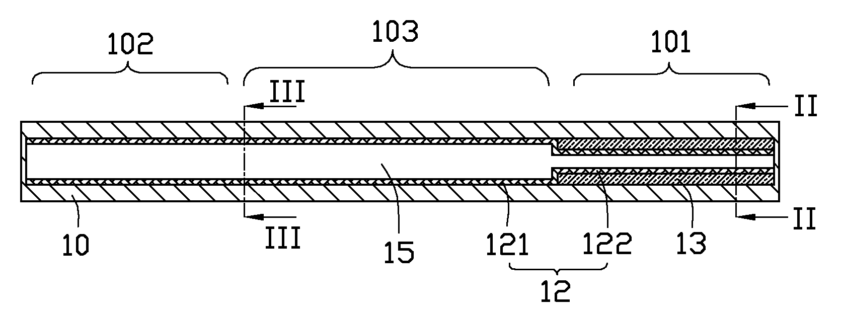
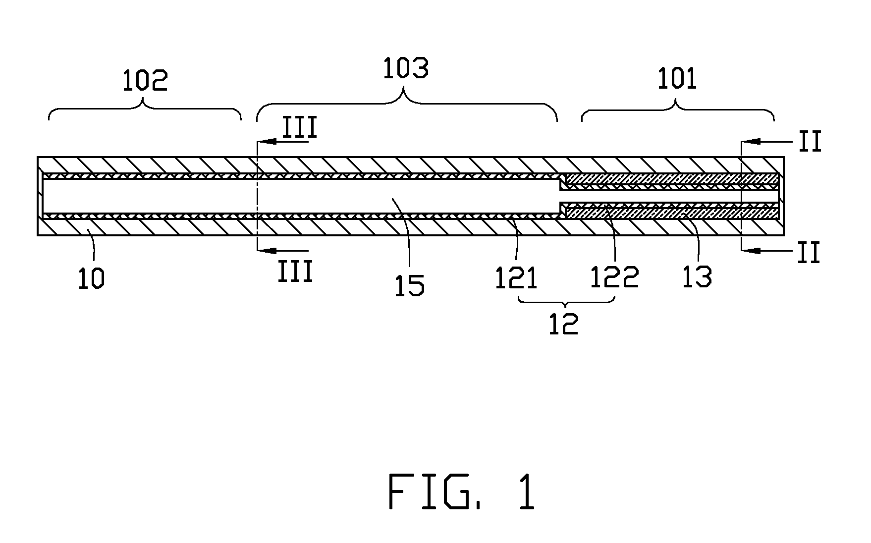
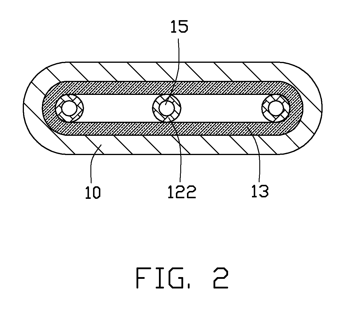
[0018]FIGS. 1-3 illustrate a heat pipe in accordance with a first embodiment of the present disclosure. The heat pipe is a plate-type heat pipe, and includes a flat tube-like metal casing 10 with two ends thereof being sealed, and a variety of elements enclosed in the metal casing 10, i.e., a wick 13, three artery meshes 12, and a working medium (not shown).

[0019]The casing 10 is made of high thermally conductive material such as copper or aluminum. A width of the casing 10 is larger than a height of the casing 10. To accommodate lightweight requirements of electronic products, the height of the casing 10 is preferably not larger than 2 mm. The casing 10 has an evaporating section 101, an opposing condensing section 102 along a longitudinal direction of the heat pipe, and an adiabatic section 103 disposed between the evaporating section 101 and the condensing section 102. The working medium is saturated in the wick 13 and the artery meshes 12. The working medium is usually selected ...


PUM


Abstract

An exemplary heat pipe includes an elongated casing, a wick, an artery mesh, and working medium filled in the casing. The casing includes an evaporating section and a condensing section. The wick is disposed within an inner wall of the evaporating section of the casing. The artery mesh includes a large portion, and a small portion with an outer diameter smaller than that of the large portion. The small portion is located within and in direct physical contact with an inner surface of the wick. The large portion is in direct physical contact with an inner wall of the condensing section of the casing. The working medium saturates the wick and the artery mesh.

Description

CROSS-REFERENCE TO RELATED APPLICATION[0001]This patent application is a divisional application of patent application Ser. No. 11 / 959,291, filed on Dec. 18, 2007, entitled “HEAT PIPE WITH COMPOSITE WICK STRUCTURE,” and assigned to the same assignee as this patent application. The disclosure of patent application Ser. No. 11 / 959,291 is incorporated herein by reference in its entirety.BACKGROUND[0002]1. Technical Field[0003]The disclosure relates generally to a heat transfer apparatus, and more particularly to a heat pipe having a composite capillary wick structure.[0004]2. Description of Related Art[0005]Heat pipes have excellent heat transfer performance due to their low thermal resistance, and are therefore an effective means for transfer or dissipation of heat from heat sources. Currently, heat pipes are widely used for removing heat from heat-generating components such as central processing units (CPUs) of computers.[0006]A heat pipe is usually a vacuum casing containing a workin...

Claims


Application Information

Patent Timeline
Patent Type & Authority Applications(United States)
IPC IPC(8): F28D15/04
CPCF28D15/046H01L2924/0002H01L2924/00
Inventor CHANG, CHANG-SHENLIU, JUEI-KHAIWANG, CHAO-HAOPEI, HSIEN-SHENG
Owner HON HAI PRECISION IND CO LTD
Why Eureka
Try Eureka