Waterproofing method for wire and wire having waterproof part formed by the waterproofing method

a technology of waterproofing method and wire, which is applied in the direction of insulated conductors, cables, cables, etc., can solve the problems of corroding the terminal in the connector, requiring unnecessary handling of ground wires, and difficult in some cases to ensure the fixed place of ground terminals, so as to increase the degree of freedom in design, reduce the need for unnecessary handling of ground wires, and increase reliability

Inactive Publication Date: 2011-03-03
SUMITOMO WIRING SYST LTD
View PDF6 Cites 51 Cited by
  • Summary
  • Abstract
  • Description
  • Claims
  • Application Information

AI Technical Summary

Benefits of technology

[0015]Since the above wire waterproofing method of the present invention can apply the waterproof treatment to the lengthwise intermediate part of the wire, unnecessary handling of the wire can be dispensed with and water penetration into a connector can be more reliably prevented by applying the waterproof treatment at the intermediate position of the wire close to the connector connecting side.
[0042]If the exposed core section to be waterproofed is fastened by crimping and connecting an intermediate crimping terminal, by being welded or by being soldered, the clearances between the strands of the core can be reliably eliminated in this crimped portion. Thus, in the case of a ground wire, water penetration from a ground terminal can be reliably blocked at the crimped position of the intermediate crimping terminal.

Problems solved by technology

In this case, a terminal connected to the other end of the ground wire is often inserted and locked in a connector and the penetrating water also enters the connector at the other end of the ground wire, which causes a problem of corroding the terminal in the connector.
In order to apply a waterproof treatment to the ground wire in this way, the ground terminal to be fixed to the vehicle needs to be crimped and connected to the end of the ground wire and, depending on vehicles, it is difficult in some cases to ensure a place where the ground terminal is fixed.
In such a case, the ground wire has to be extended up to the place where the ground terminal can be fixed and unnecessary handling of the ground wire is required.
In addition, if the ground wire is unnecessarily made longer, a possibility of the ground wire being interfered with and damaged by an external interfering member is increased by that much.
Even if a waterproof treatment is applied at an end position connected with the ground terminal, water may enter at a damaged position and penetrate to a connector connecting portion at the other end of the ground wire if the ground wire is damaged at an intermediate position.
Since this jig needs to be provided for each size of ground terminals, equipment cost increases, which leads to an increase of production cost.

Method used


Image

  • Waterproofing method for wire and wire having waterproof part formed by the waterproofing method
  • Waterproofing method for wire and wire having waterproof part formed by the waterproofing method
  • Waterproofing method for wire and wire having waterproof part formed by the waterproofing method

Examples


first embodiment

[0077]FIGS. 5 and 6 show a

[0078]In the first embodiment, an intermediate crimping terminal 30 having a U-shaped cross section is crimped and connected to the exposed core section 18.

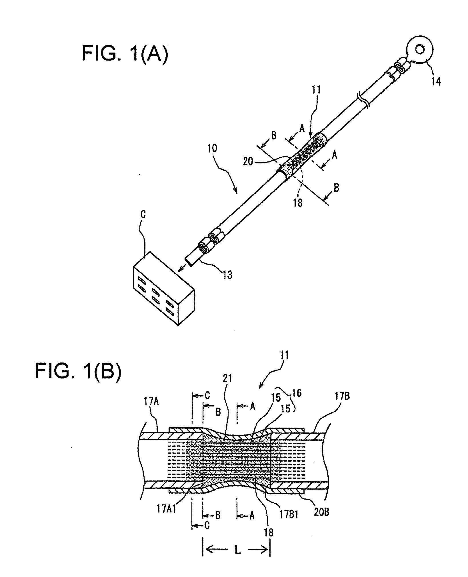
[0079]A waterproofing agent reservoir 31 having a required length is provided between one end 30a of the intermediate crimping terminal 30 in a lengthwise direction and the slit end surface 17A1 of the insulating coating layer 17A.

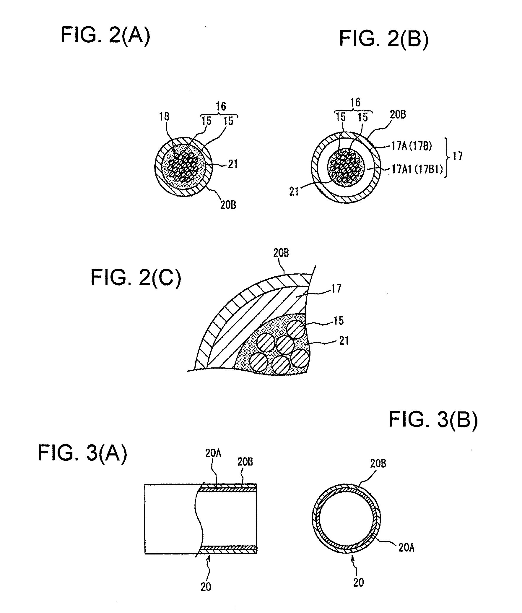
[0080]When the heat shrinkable tube 20 is heated to melt the inner layer tube 20B, thereby bringing the waterproofing agent 21 into a molten state, the molten waterproofing agent 21 first flows into the waterproofing agent reservoir 31 and stays therein.

[0081]The waterproofing agent 21 flowed into the waterproofing agent reservoir 31 is infiltrated into clearances between the strands 15 in the waterproofing agent reservoir 31.

[0082]If negative pressure is simultaneously introduced from the end (i.e. end connected with the connector connecting terminal 13) of the insulating coat...

second embodiment

[0086]FIGS. 7 and 8 show a

third embodiment

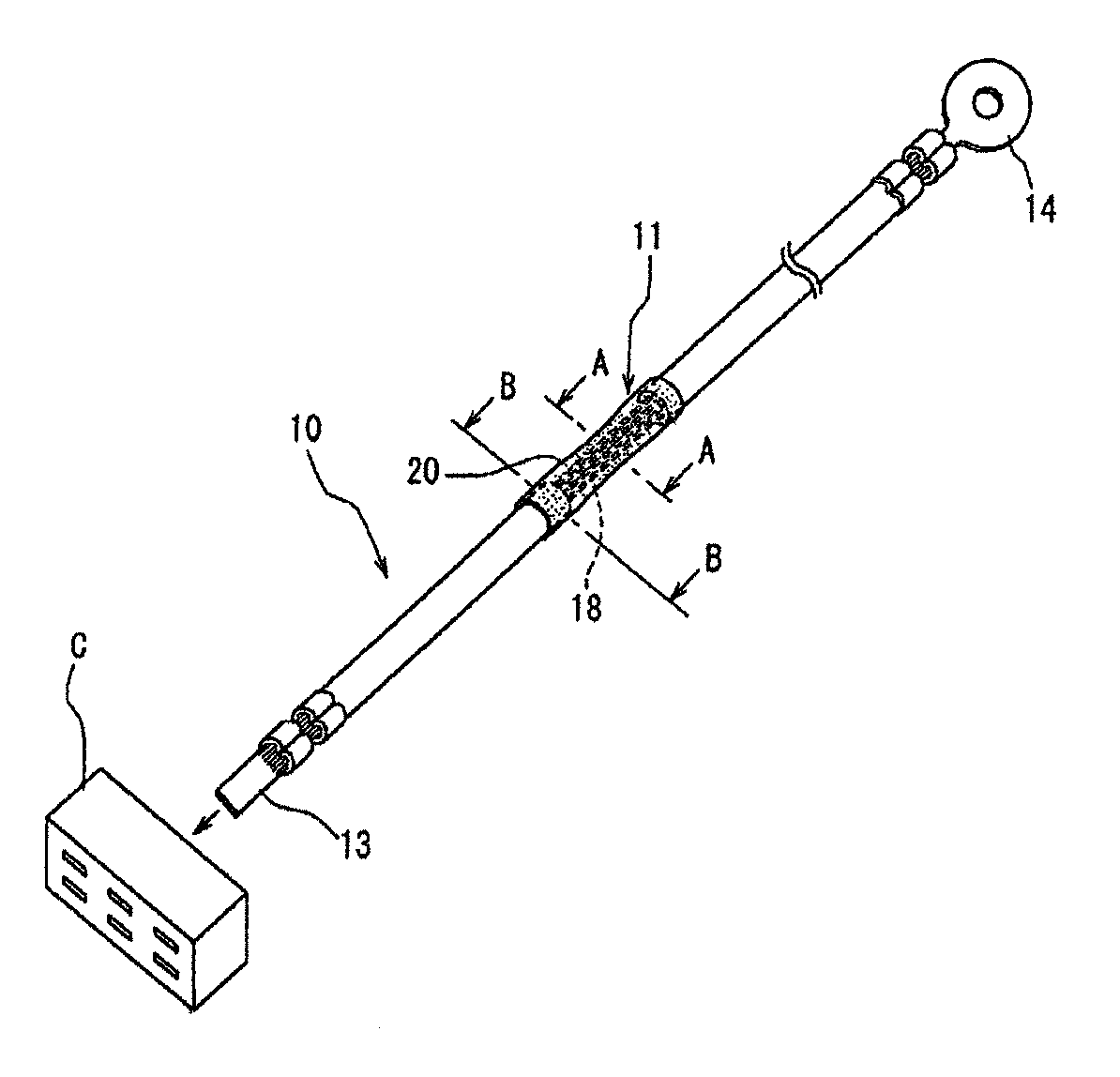
[0087]A wire 10 of the third embodiment is a power wire and has an end on the side of an insulating coating layer 17A connected with a connector connecting terminal 13 to be connected with a unit 60 accommodated in an electrical connection box arranged in a water susceptible area, which is an engine compartment, and the other end connected with a fuse terminal 63 of an electrical connection box 62 arranged in a vehicle interior as shown in FIG. 8. The wire 10 is also spliced to an end of a wire 65 to be connected with another unit 64 in a water free area in the vehicle interior. In the case of forming a waterproof part 70 in a water susceptible area S in the engine compartment between this spliced portion 66 and the connector connecting terminal of the wire 10, a construction shown in FIG. 7 is employed.

[0088]In this embodiment, strands 15 of an exposed core section 18 are welded by ultrasonic welding to form a welded potion 71 in which there are no clearances between the strands. A...


PUM

PropertyMeasurementUnit
temperatureaaaaaaaaaa
shrinkage temperatureaaaaaaaaaa
viscosityaaaaaaaaaa

Abstract

A waterproofing method is provided for a wire to be arranged in a water susceptible area of a vehicle. An insulating coating layer is removed in a lengthwise intermediate part of the wire to expose a core. A heat shrinkable tube with an inner layer made of a hot-melt waterproofing agent is mounted on the exposed core section and parts of the insulating coating layer adjacent to the exposed core section and heated. As a result, the hot-melt waterproofing agent of the inner layer is melted and infiltrates into clearances between strands of the exposed core section. In addition, negative pressure is introduced into the inside of the insulating coating layer from an end of the wire, thereby sucking the waterproofing agent into the inside of the insulating coating layer to infiltrate the waterproofing agent also between the strands of the core inside the insulating coating layer.

Description

BACKGROUND OF THE INVENTION[0001]1. Field of the Invention[0002]The present invention relates to a wire waterproofing method and a wire having a waterproof part formed by the waterproofing method and is particularly designed to be able to apply a waterproof treatment at an arbitrary position of a wire arranged in a water susceptible area of a vehicle.[0003]2. Description of the Related Art[0004]Conventionally, if a wiring harness is arranged along a water susceptible area of a vehicle such as a car or a motorcycle, a ground terminal is crimped and connected to an end of a ground wire of the wiring harness and grounded by being bolted to a vehicle body in many cases. In this case, if the fixed position of the ground terminal is located in a water susceptible area, water enters the inside of the ground wire through an exposed core section crimped and connected to the ground terminal and penetrates to the other end of the ground terminal through clearances of a core made up of a multit...

Claims


Application Information

Patent Timeline
Patent Type & Authority Applications(United States)
IPC IPC(8): H02G3/00B23K20/10H02G15/02
CPCB60R16/0207H01B7/285H01B3/441H02G15/013H01R4/72
Inventor SAWAMURA, NAOHITO
Owner SUMITOMO WIRING SYST LTD
Why Eureka
Try Eureka