Waterproofing method for electric wire and the wire having waterproof part formed by the waterproofing method

a technology of waterproofing method and electric wire, which is applied in the direction of insulated conductors, cables, conductors, etc., can solve the problems of corroding the terminal in the connector, requiring unnecessary ground wire handling, and difficult in some cases to ensure a place, so as to increase the degree of freedom in design, prevent water penetration, and avoid unnecessary ground wire handling

Inactive Publication Date: 2010-08-26
SUMITOMO WIRING SYST LTD
View PDF8 Cites 24 Cited by
  • Summary
  • Abstract
  • Description
  • Claims
  • Application Information

AI Technical Summary

Benefits of technology

[0043]Specifically, since the waterproofing agent can be reliably infiltrated and filled into the clearances between the stands of the core in the waterproof part formed by the inventive waterproofing method, water penetration can be prevented even if the waterproof part is left exposed. However, it is preferable to protect the waterproof part by winding the waterproof sheet or the waterproof tape in order to protect the waterproof part from an external interfering member and to prevent the contact with an external interfering member when an intermediate crimping terminal is mounted.
[0044]As described above, in the wire waterproofing method of the present invention, the waterproof treatment can be applied at an arbitrary lengthwise position of the wire, thereby increasing a degree of freedom in design. In addition, since no waterproof treatment needs to be applied at the position of the ground terminal as disclosed in JP 2006-228709 and JP 2007-134054, the waterproof treatment can be applied not only to a wire connected with a ground terminal to be fixed to a body panel, but also any arbitrary wire. Thus, unnecessary handling of the wire can be dispensed with. Further, since the waterproof part can be formed at the intermediate position close to the connector connecting side where the waterproof treatment is necessary, the connector connecting side can be waterproofed with increased reliability.
[0045]Further, since the waterproof treatment is applied at the intermediate position of the wire, the jig for positioning the ground terminal disclosed in JP 2007-134054 becomes unnecessary and, hence, equipment cost for the waterproof treatment can be reduced.
[0046]If the intermediate crimping terminal is crimped and connected to the exposed core section to be waterproofed, the clearances between the strands of the core can be reliably eliminated in this crimped part. Also in the case of welding, fusing or soldering the intermediate terminal, water penetrating between the strands can be reliably blocked by eliminating the clearances between the strands. In the case of an intermediate crimping terminal, it can be commonly used if core constructions are substantially same. Therefore, the number of parts can be reduced.

Problems solved by technology

In this case, a terminal connected to the other end of the ground wire is inserted and locked in a connector in many cases and the penetrating water also enters the connector at the other end of the ground wire, which causes a problem of corroding the terminal in the connector.
However, depending on vehicles, it is difficult in some cases to ensure a place where a ground terminal is fixed.
In such a case, the ground wire has to be extended up to the place where the ground terminal can be fixed and unnecessary handling of the ground wire is required.
In addition, if the ground wire is unnecessarily made longer, a possibility of the ground wire being interfered with and damaged by an external interfering member is increased by that much.
Even if a waterproof treatment is applied at an end position connected with the ground terminal, water may enter at a damaged position and penetrate to a connector connecting portion at the other end of the ground wire if the ground wire is damaged at an intermediate position.
Since this jig needs to be provided for each size of ground terminals, equipment cost increases, which leads to an increase of production cost.

Method used


Image

  • Waterproofing method for electric wire and the wire having waterproof part formed by the waterproofing method
  • Waterproofing method for electric wire and the wire having waterproof part formed by the waterproofing method
  • Waterproofing method for electric wire and the wire having waterproof part formed by the waterproofing method

Examples


first embodiment

[0061]FIGS. 1 to 3 show a

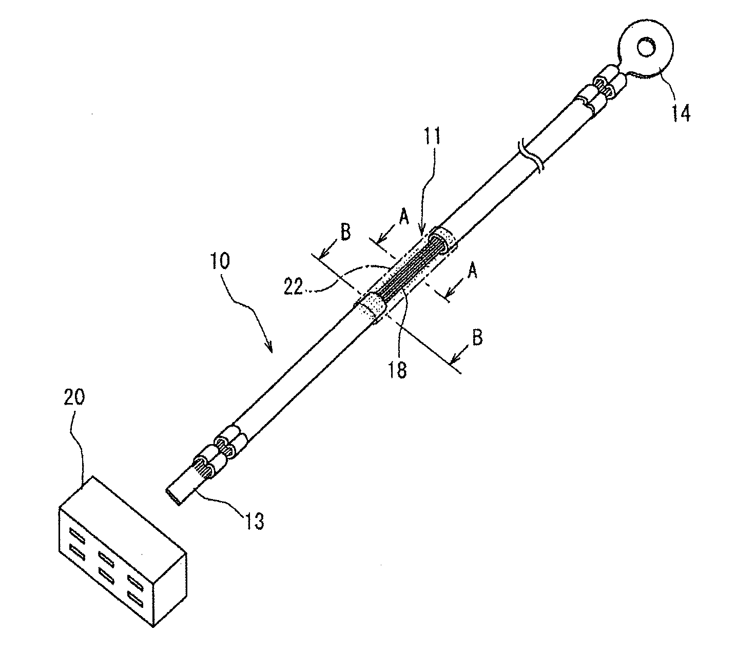
[0062]In the first embodiment, a wire 10 for a ground circuit arranged in a water susceptible area is provided with a waterproof part 11.

[0063]The wire 10 has one end crimped and connected to a terminal 13, which is to be inserted and locked in a connector 20, and the other end crimped and connected to a ground terminal 14. The waterproof part 11 is formed at an intermediate position closer to the connector connecting terminal 13 than to the ground terminal 14.

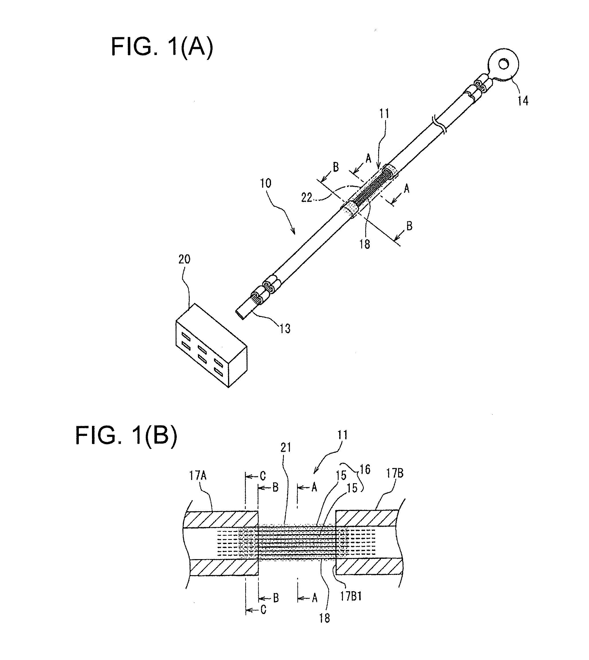
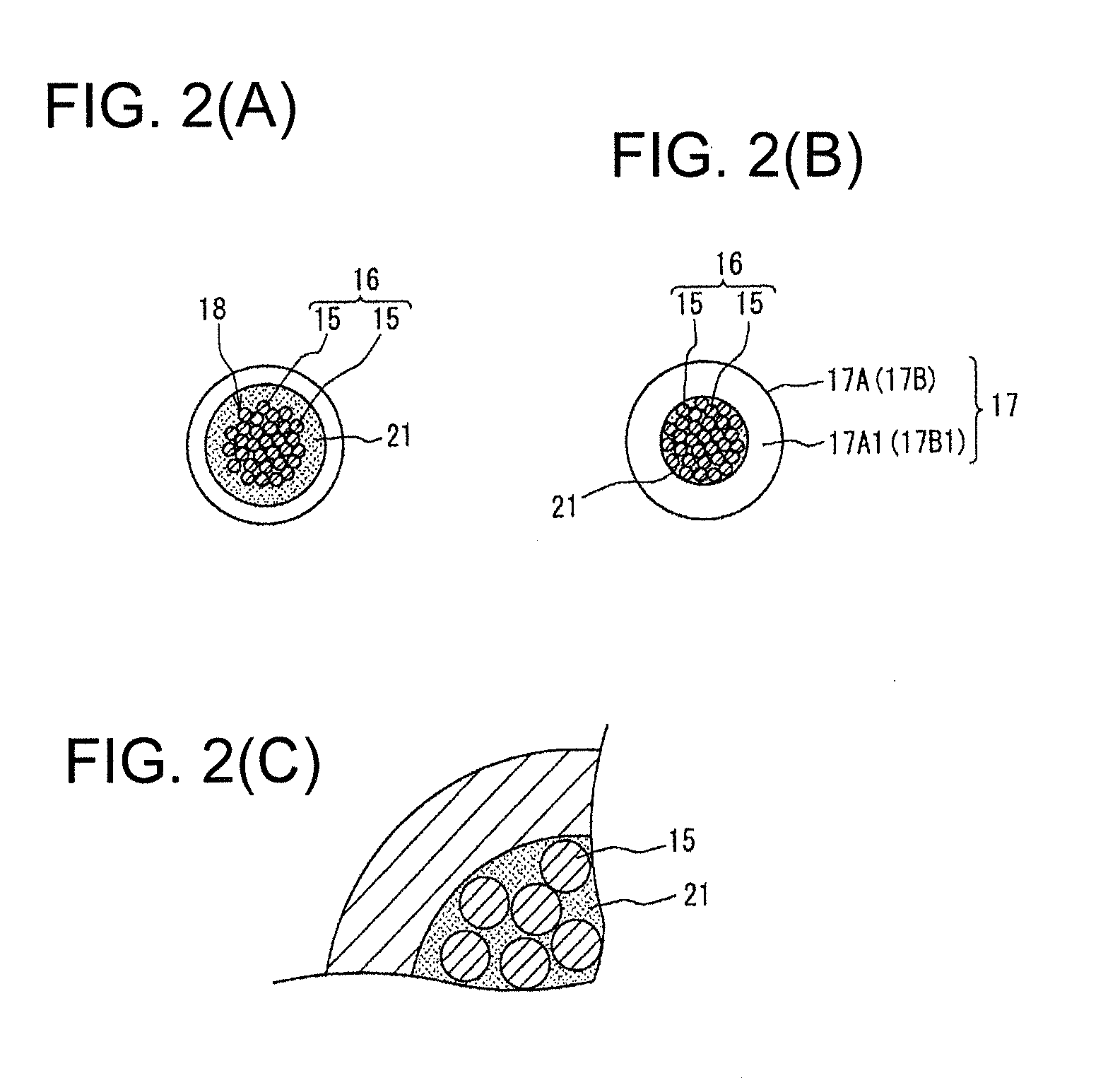
[0064]As shown in FIG. 2(B), the wire 10 is composed of a core 16 formed by twisting a multitude of strands 15 and an insulating coating layer 17 surrounding the core 16 and made of insulating resin.

[0065]In the waterproof part 11 of the wire 10, a slit is formed in the insulating coating layer 17 and an insulating resin layer 17B at a side of the slit toward the ground terminal is moved to form an exposed core section 18 having the insulating resin layer removed between a slit end surface 17B1 of the ...

second embodiment

[0080]FIGS. 4(A) and 4(B) show a

[0081]In the above first embodiment, the negative pressure is introduced to the insides of the insulating coating layers 17A, 17B from the opposite ends of the wire 10 and the waterproofing agent 21 is sucked into the clearances between the strands 15 in the exposed core section 18 and into the insides of the insulating coating layers 17A, 17B by the negative pressure. However, in the second embodiment, the exposed core section 18 is loaded with pressure air to press the waterproofing agent 21 into the clearances between the strands 15 of the exposed core section 18 and into the insides of the insulating coating layers 17A, 17B at the opposite sides.

[0082]As shown in FIG. 4, a pressurized container 50 is provided to seal the exposed core section 18 and the insulating resin layers 17A, 17B at the opposite sides. The pressurized container 50 includes a lower container 51 and an upper container 52 hinged to the lower container 51 and is formed with semic...

third embodiment

[0092]FIGS. 5 and 6 show a

[0093]In the third embodiment, an intermediate crimping terminal 30 having a U-shaped cross section is crimped and connected to the exposed core section 18.

[0094]A waterproofing agent reservoir 31 having a required length is provided between one end 30a of the intermediate crimping terminal 30 in a lengthwise direction and the slit end surface 17A1 of the insulating coating layer 17A.

[0095]The waterproofing agent 21 is dropped into the waterproofing agent reservoir 31 from above and negative pressure is introduced from the end of the insulating coating layer 17A (i.e. end crimped and connected to the connector connecting terminal 13) as in the first embodiment to suck the waterproofing agent 21 from the slit end surface 17A1 in the insulating coating layer 17A.

[0096]An exposed core section is formed between another end 30b of the intermediate crimping terminal 30 and the slit end surface 17B1 of the other insulating coating layer 17B. However, since the ins...


PUM

PropertyMeasurementUnit
water susceptible areaaaaaaaaaaa
pressureaaaaaaaaaa
insulatingaaaaaaaaaa

Abstract

A waterproofing method is provided for a wire to be arranged in a water susceptible area of a vehicle. The method includes removing an insulating coating layer in a lengthwise intermediate part of the wire to expose a core. A fluid waterproofing agent then is dropped to an exposed core section. Negative pressure then is introduced into the inside of the insulating coating layer from wire ends to suck the waterproofing agent into the inside of the insulating coating layer. Alternatively the exposed core section is loaded with pressure air to press the waterproofing agent into the inside of the insulating coating layer. Thus the waterproofing agent is infiltrated between the strands inside the insulating coating layer.

Description

BACKGROUND OF THE INVENTION[0001]1. Field of the Invention[0002]The present invention relates to a wire waterproofing method and a wire having a waterproof part formed by the waterproofing method and is particularly designed to be able to apply a waterproof treatment at an arbitrary position of a wire arranged in a water susceptible area of a vehicle.[0003]2. Description of the Related Art[0004]Conventionally, there have been cases where a wiring harness is arranged along a water susceptible area of a vehicle such as a car or a motorcycle. A ground terminal crimped and connected to an end of a ground wire of the wiring harness is grounded by being bolted to a vehicle body in many cases.[0005]If the vehicle, to which the ground terminal is fixed, is located in a water susceptible area, water enters the inside of the ground wire through an exposed core section of the wire crimped and connected to the ground terminal and penetrates to the other end of the ground terminal through cleara...

Claims


Application Information

Patent Timeline
Patent Type & Authority Applications(United States)
IPC IPC(8): H01B7/285H01R43/00
CPCH01B7/285Y10T29/49174H02G15/013H02G1/14
Inventor ARAI, MASARU
Owner SUMITOMO WIRING SYST LTD
Why Eureka
Try Eureka