

Fastener for elongated component
- Summary
- Abstract
- Description
- Claims
- Application Information
AI Technical Summary
Benefits of technology
Problems solved by technology
Method used
Image

Examples
Embodiment Construction
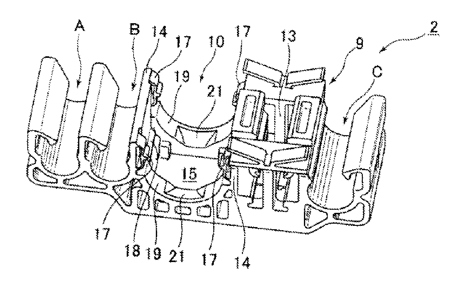
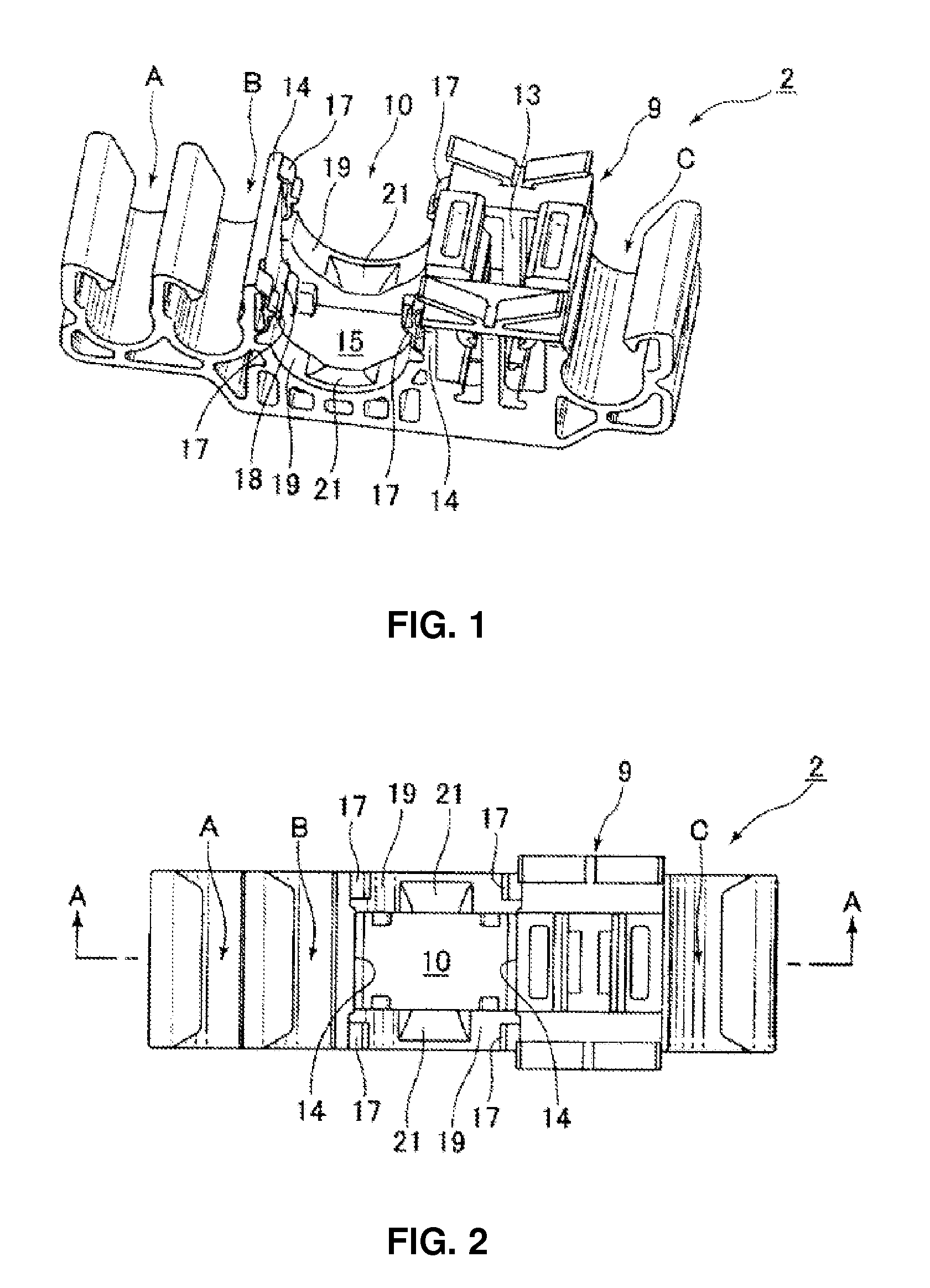
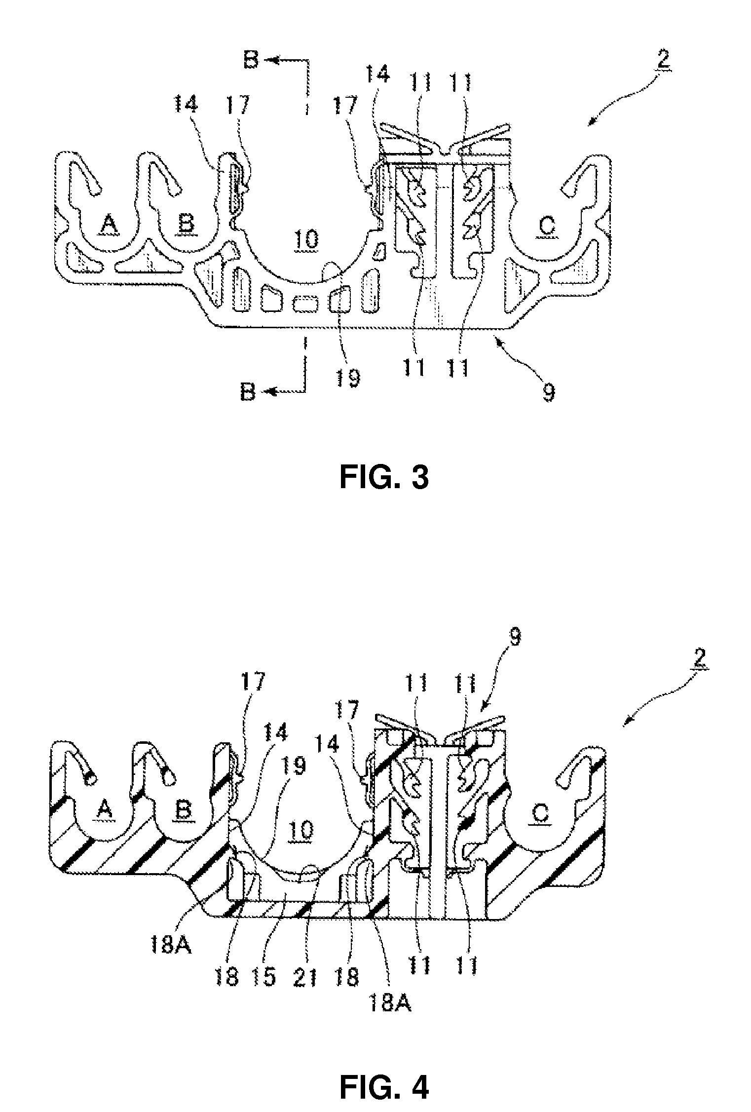
[0040]The following is an explanation with reference to the figures of the fastener for an elongated component 1 in the first embodiment of the present invention. The fastener 1 consists of the body 2 shown in FIG. 1 through FIG. 5 and the clamp 3 shown in FIG. 6 through FIG. 9, which is separate from the body 2. As shown in FIG. 10 through FIG. 17, the clamp 3 is connected to the body 2. The body 2 and the clamp 3 are molded as separate components, but both components are integrally molded from a hard synthetic resin material. In the embodiment shown in the figures, clamps A, B and C common in the art are integrally molded in the body 2 to hold pipes separate from the pipe held by the clamp 3. Clamps A through C may or may not be used, but any other pipes are held parallel to the pipe held by the clamp 3.
[0041]In the fastener 1, as shown in FIG. 18, the pipe 5 serving as the elongated component (as well as the other pipes AA, BB, CC) are held by the clamp 3 (as well as clamps A, B,...
PUM
 Abstract
Description
Claims
Application Information