Shock absorber having compressible fluid

a technology of compressible fluid and shock absorber, which is applied in the direction of vibration dampers, springs/dampers, springs, etc., can solve the problems of high power consumption and high wear, high valve and electronics costs, and inability to use as shock absorbers, etc., and achieve the effect of improving the damping characteristi

Inactive Publication Date: 2011-03-03
KNORR-BREMSE SYST FUER NUTZFAHRZEUGE GMBH
View PDF7 Cites 30 Cited by
  • Summary
  • Abstract
  • Description
  • Claims
  • Application Information

AI Technical Summary

Benefits of technology

[0016]It is the object of the exemplary embodiments and/or exemplary methods of the prese

Problems solved by technology

The problem is that such regulators use complex hardware and software and very rapid regulators result in a high power consumption and high wear.
For most applications in vehicles, the damping

Method used


Image

  • Shock absorber having compressible fluid
  • Shock absorber having compressible fluid
  • Shock absorber having compressible fluid

Examples


Embodiment Construction

[0068]In the following description of the exemplary embodiments of the present invention, identical or similar reference numerals are used for the similarly acting elements, which are shown in the various drawings, a repeated description of these elements being omitted.

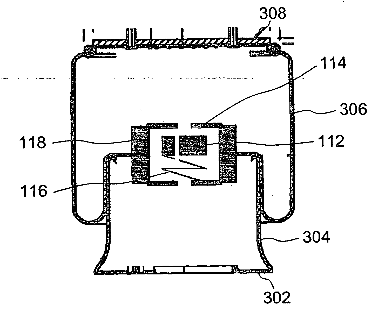
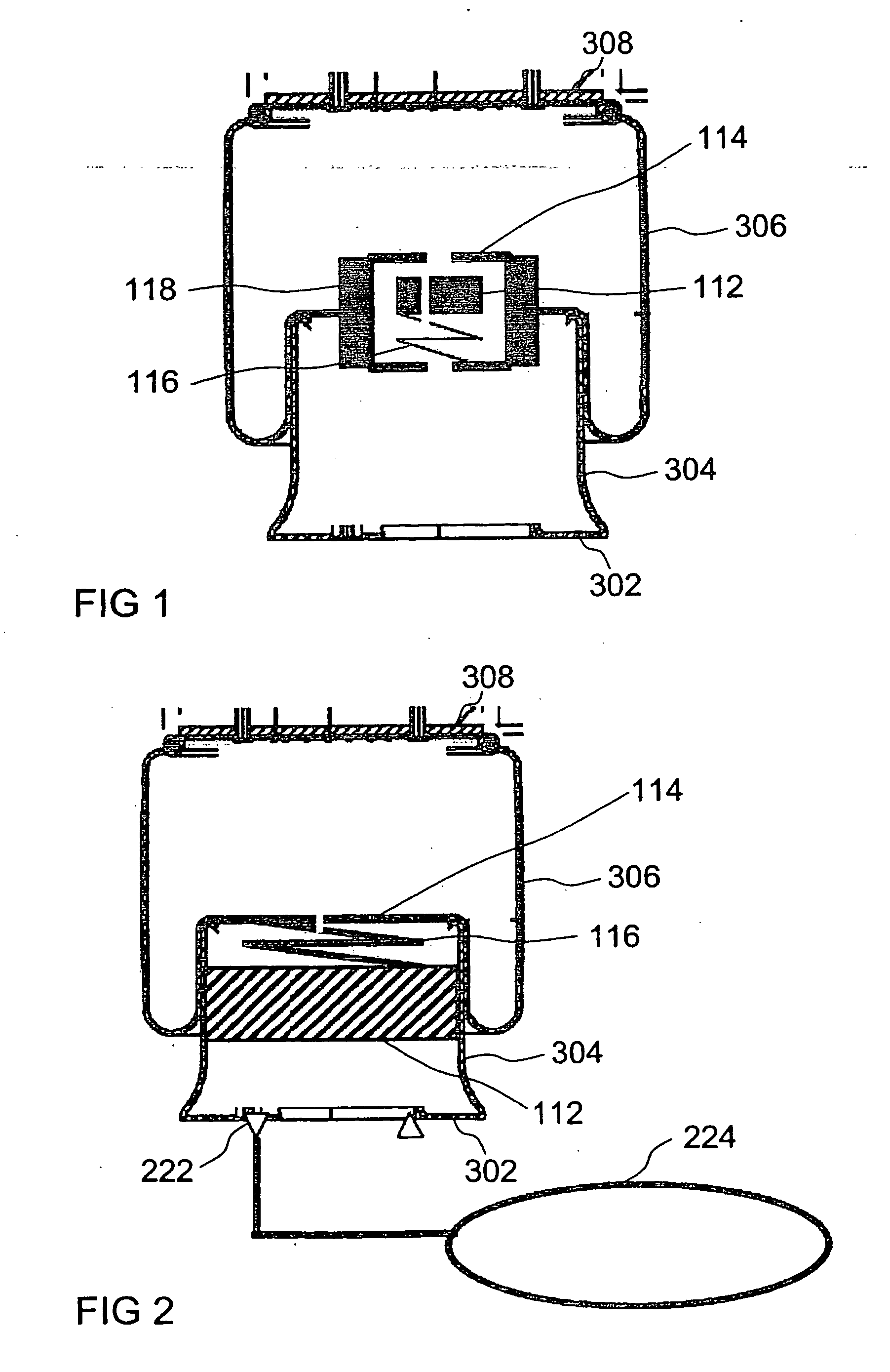
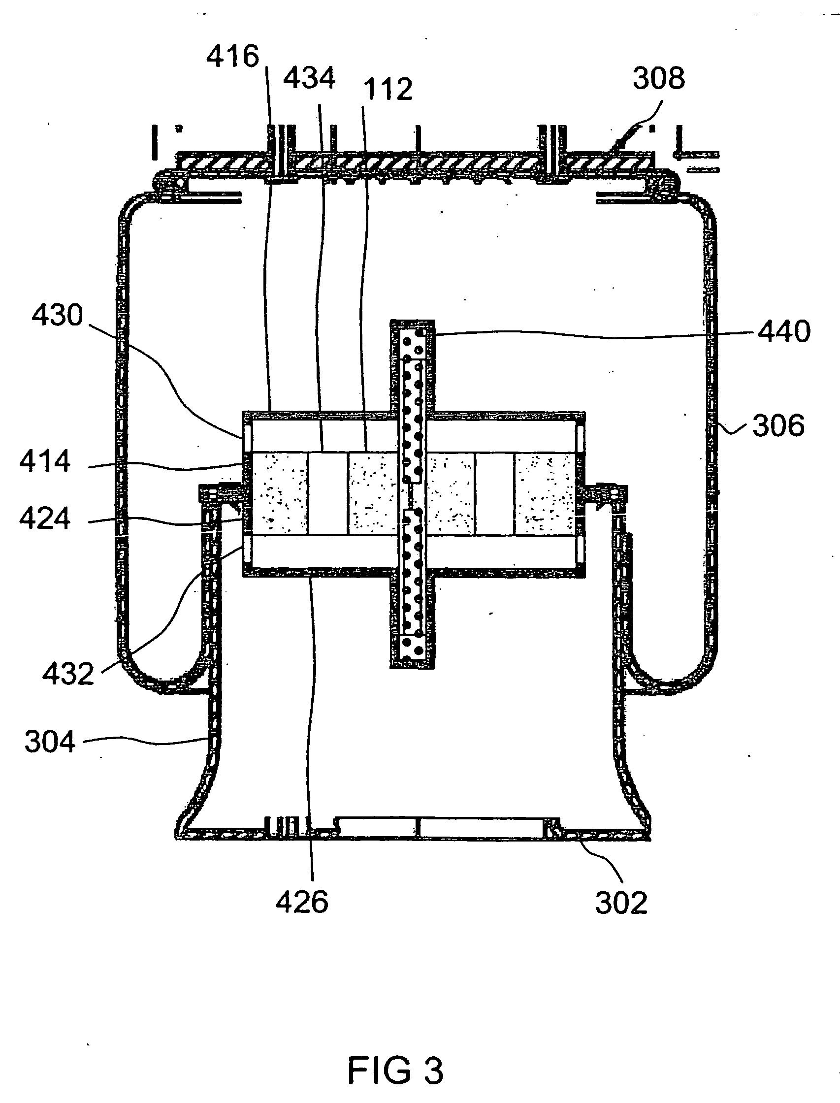
[0069]FIG. 1 shows a shock absorber according to an exemplary embodiment of the present invention. The shock absorber may be the air bellows described on the basis of FIG. 3, having features 302, 304, 306, 308. According to the exemplary embodiments and / or exemplary methods of the present invention, the bellows additionally has a sprung mass 112.

[0070]Sprung mass 112 is situated inside the bellows in such a way that it may influence a fluid flow between the bellows and the auxiliary volume located in the bellows piston. The fluid flow arises, for example, in the event of a compression or relaxation of the bellows. The characteristic frequency of sprung mass 112 is tuned to the characteristic frequencies of the vehicle...


PUM


Abstract

A shock absorber for a vehicle, having a bellows piston, bellows, and a fluid as the damping medium. The shock absorber has a first partition wall, which is situated on the bellows piston, and is implemented to separate a volume area of the bellows piston from a volume area of the bellows. The first partition wall has a first opening, which is implemented to limit a fluid flow between the volume area of the bellows piston and the volume area of the bellows. The shock absorber further has a sprung mass, which is situated inside the shock absorber to influence the fluid flow inside the shock absorber.

Description

FIELD OF THE INVENTION[0001]The present invention relates to a shock absorber having a compressible fluid as the damping medium.BACKGROUND INFORMATION[0002]In vehicles, shock absorber regulators are currently typical. In such regulators, the goal is pursued of stabilizing either the bodywork or the unsprung masses. A regulator typically includes sensors, electronics, and actuators. The switching speed receives particular significance. The more rapidly a movement state may be sensed, analyzed, and readjusted by the actuator, the better. However, parameters such as power consumption and forces are to be considered. Ultimately, the regulation is always only a response to an undesired state. The problem is that such regulators use complex hardware and software and very rapid regulators result in a high power consumption and high wear. However, at the same time the stabilizing of the unsprung masses requires a high speed in particular, because their characteristic frequency is approximat...

Claims


Application Information

Patent Timeline
IPC IPC(8): F16F9/512F16F9/34F16F9/05
CPCF16F9/5126F16F9/0472
Inventor NABER, THOMAS
Owner KNORR-BREMSE SYST FUER NUTZFAHRZEUGE GMBH
Why Eureka
Try Eureka