Electronic ballast device and operation method thereof

a technology of electronic ballast and operation method, which is applied in the direction of electrical equipment, instruments, light sources, etc., can solve the problems of affecting the operation of the preheating function, the complexity of the preheating sweep frequency circuit, and the inability to maintain the preheating function, so as to reduce the complexity and improve the preheating function. , the effect of reducing the complexity

Inactive Publication Date: 2011-03-03
INERGY TECH
View PDF4 Cites 2 Cited by
  • Summary
  • Abstract
  • Description
  • Claims
  • Application Information

AI Technical Summary

Benefits of technology

[0007]Accordingly, one aspect of the invention provides an electronic ballast device, which can reduce the complex and improve the preheating function.
[0009]Consequently, not only can the electronic ballast device be used with fewer electronic elements but also increase the utility and stability.

Problems solved by technology

Nevertheless, the conventional sweep frequency circuit for preheating is too complex, and the capacitance in the circuit takes too much time to be charged or release the stored charges.
Consequently, how to modify and improve the sweep frequency circuit so as to decrease the cost and maintain the preheating function becomes a significant issue.

Method used


Image

  • Electronic ballast device and operation method thereof
  • Electronic ballast device and operation method thereof
  • Electronic ballast device and operation method thereof

Examples


Embodiment Construction

[0016]In the following detailed description, for purposes of explanation, numerous specific details are set forth in order to provide a thorough understanding of the disclosed embodiments. It will be apparent, however, that one or more embodiments may be practiced without these specific details. In other instances, well-known structures and devices are schematically shown in order to simplify the drawings.

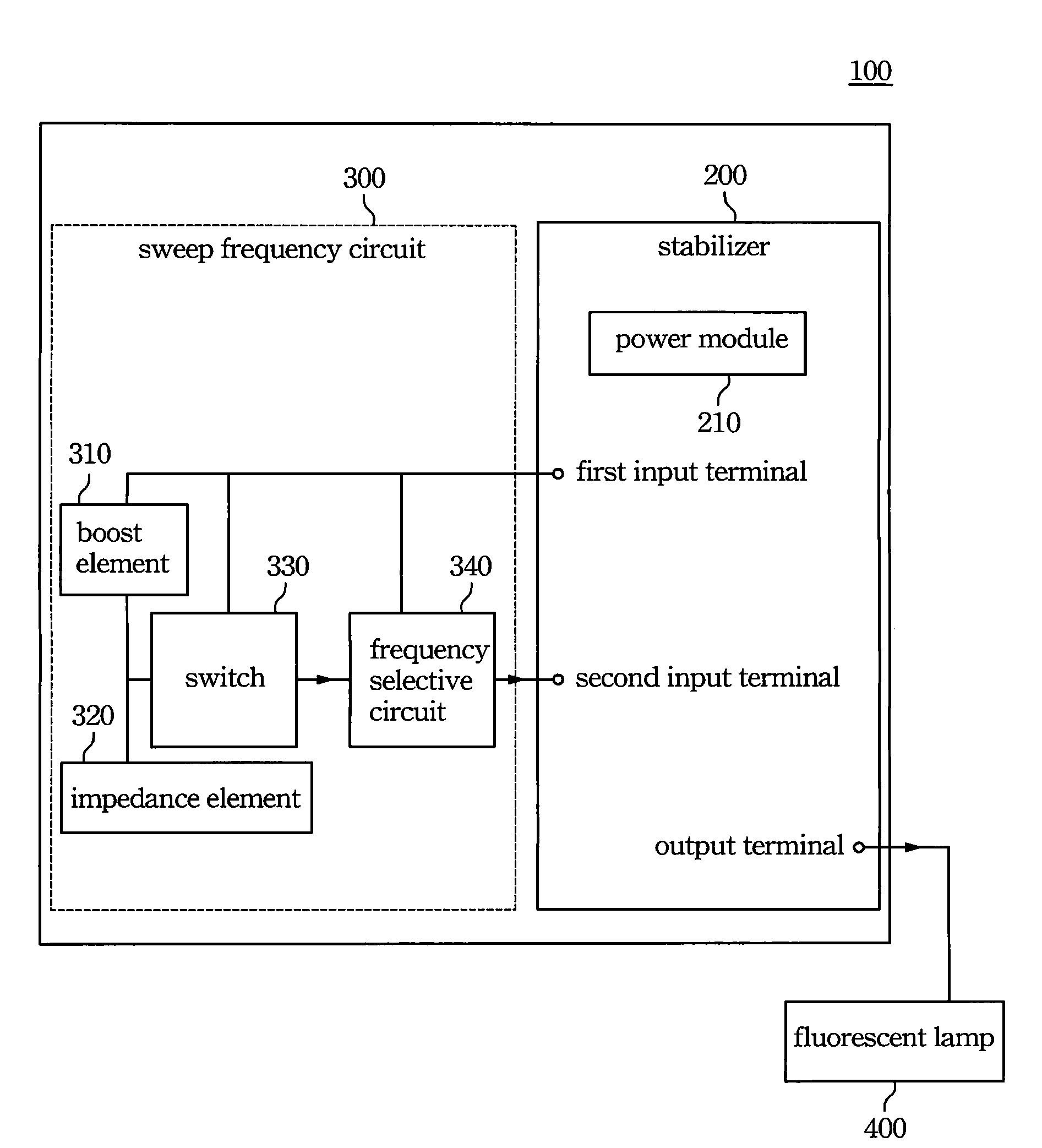
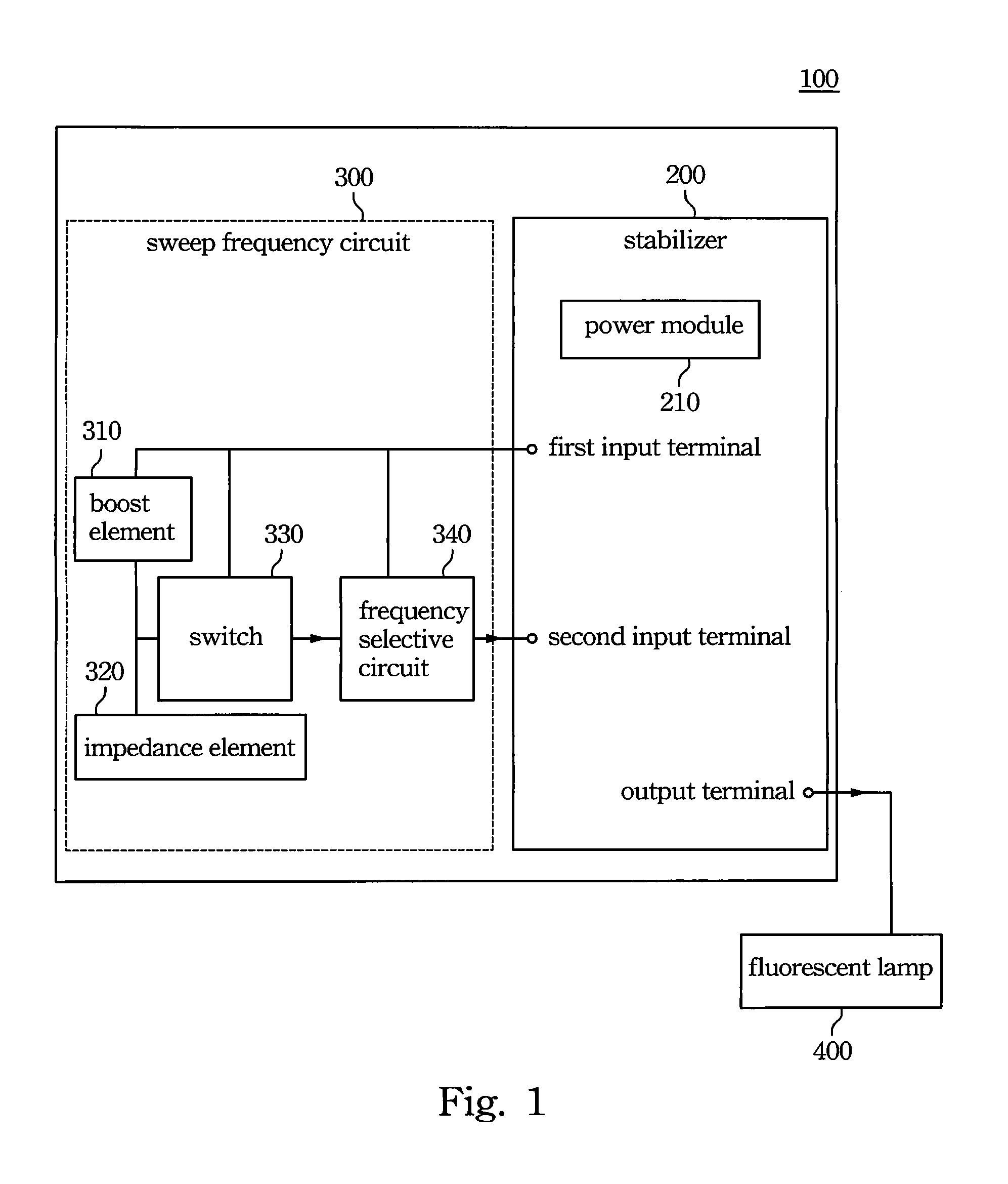
[0017]FIG. 1 is a functional block diagram of an electronic lamp ballast device according to an embodiment of the invention. With reference to FIG. 1, an electronic ballast device 100 includes a stabilizer 200 and a sweep frequency circuit 300 for preheating. The stabilizer 200 includes a first input terminal, a second input terminal and an output terminal connected to a fluorescent lamp 400. The stabilizer 200 further includes a power module 210 used for providing a working voltage to the first input terminal. The sweep frequency circuit 300 for preheating includes a boost element...


PUM


Abstract

An electronic ballast device includes a stabilizer and a sweep frequency circuit for preheating. The stabilizer includes a first input terminal, a second input terminal and an output terminal connected to a fluorescent lamp. The sweep frequency circuit includes a boost element, an impedance element, a switch and a frequency selective circuit. The boost element includes a first end and a second end separately electrically connected to the first input terminal and the impedance element. The switch includes an input terminal electrically connected to the common contact point of the boost element and the impedance element, an output terminal and a reference voltage input terminal electrically connected to the common contact point of the boost element and the stabilizer. Furthermore, the frequency selective circuit is electrically connected to the output terminal of the switch, the first input terminal of the stabilizer and the second input terminal of the stabilizer.

Description

BACKGROUND[0001]1. Field of Invention[0002]The present invention relates to an electronic ballast device. More particularly, the present invention relates to an electronic lamp ballast device.[0003]2. Description of Related Art[0004]Compared with the incandescent light bulb, the advantages of the fluorescent lamp are the higher luminous efficacy, the longer life and the lower heat. Therefore, the fluorescent lamp replaces the incandescent light bulb quickly, and becomes the mainstream.[0005]Generally speaking, the fluorescent lamp has no filament running through it. Instead, cathodes at each end send current through mercury vapors sealed in the tube. Ultraviolet radiation is produced as electrons from the cathodes knock mercury electrons out of their natural orbit. Some of the displaced electrons settle back into orbit, throwing off the excess energy absorbed in the collision. Almost all of this energy is in the form of ultraviolet radiation. To turn this radiation into visible ligh...

Claims


Application Information

Patent Timeline
Patent Type & Authority Applications(United States)
IPC IPC(8): H05B41/36
CPCH05B41/382H05B41/295
Inventor CHEN, CHING-PIAO
Owner INERGY TECH
Why Eureka
Try Eureka