System for storing electrical energy

Inactive Publication Date: 2011-03-03
MACDONALD R IAN +1
View PDF5 Cites 14 Cited by
  • Summary
  • Abstract
  • Description
  • Claims
  • Application Information

AI Technical Summary

Benefits of technology

[0009]In accordance with an aspect of this invention there is provided, a system for storing electrical energy comprising an electrically powered evaporator for evaporating water from a first solution at a gre

Problems solved by technology

It is difficult to alter the supply of electricity from an electricity distribution grid to adapt to changes in local demand.
However it is difficult to store energy on the scale required, which may be of the order of gigaWatt hours.
Places where energy storage is required may not have suitable topology for the construction of a large elevated water reservoir.
Very large and costly mining operations are required, as the caverns must be placed hundreds of metres underground.
Such installations require economics of scale and are suitable only for very large power storage requirements

Method used


Image

  • System for storing electrical energy
  • System for storing electrical energy
  • System for storing electrical energy

Examples


Example

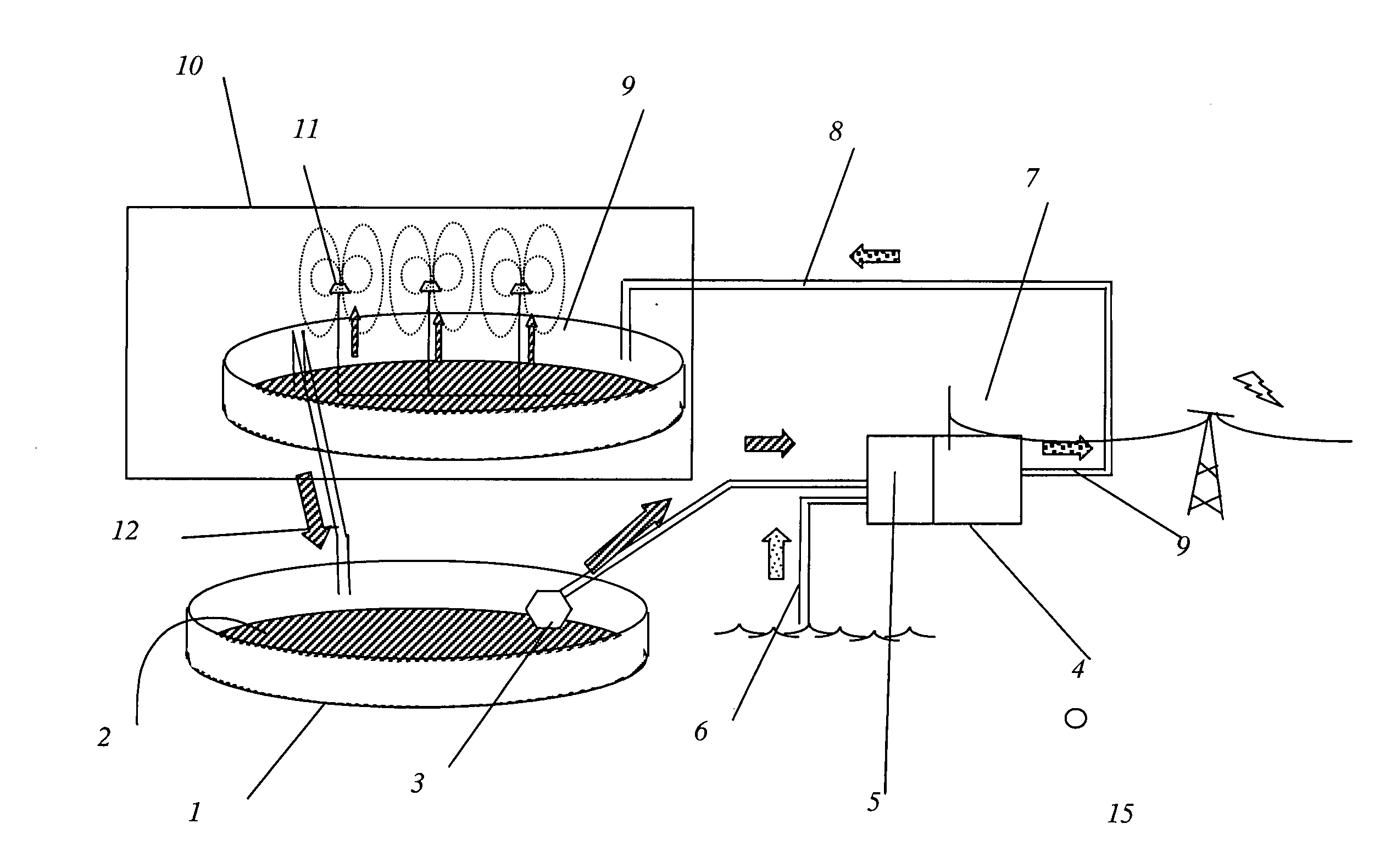
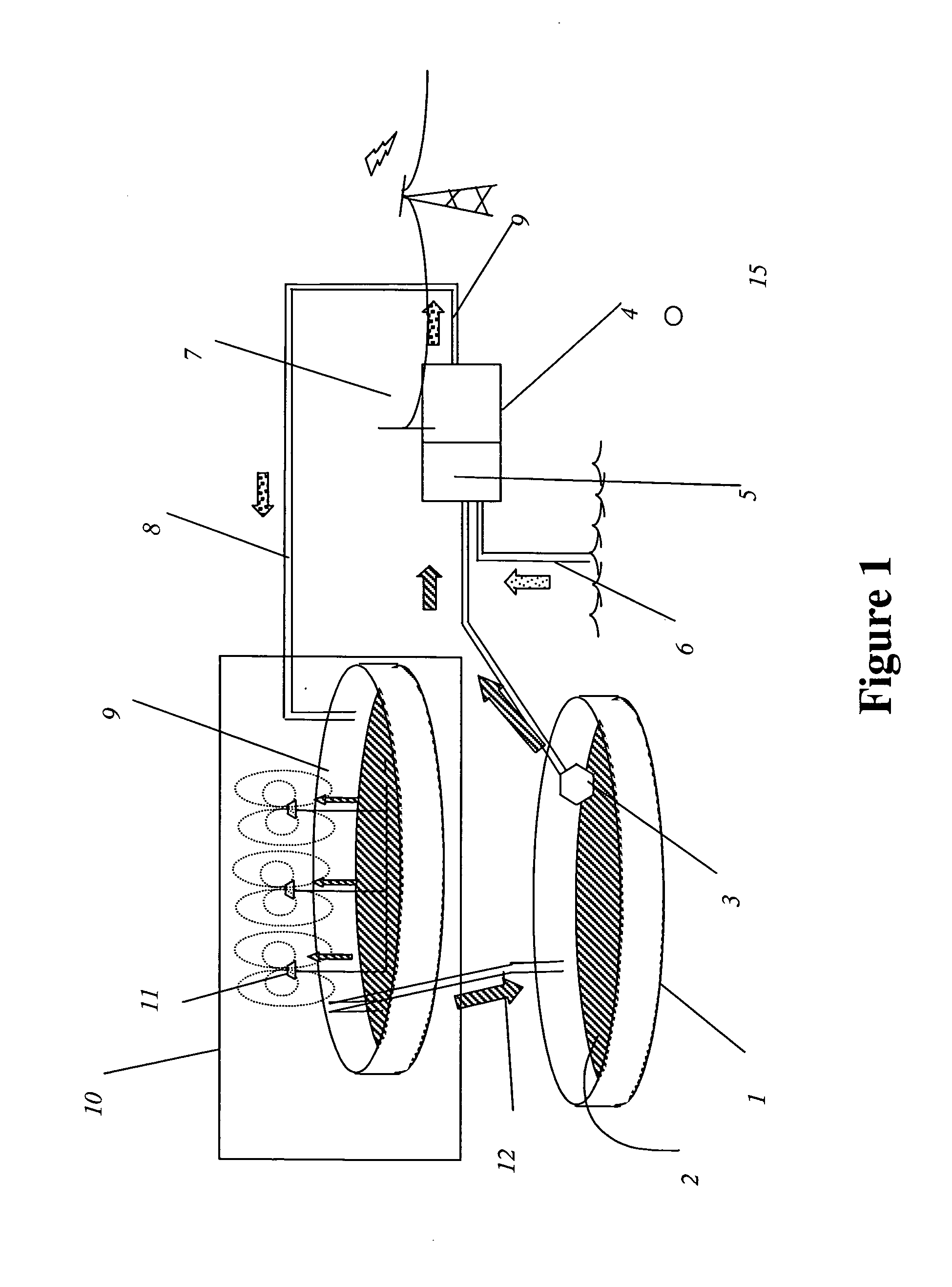
[0027]Electrical power may be derived from the difference in concentration of two instances of the same solution, typically salt dissolved in water, using means for power generation. Means for power generation includes a concentration based electrical generator which may be a pressure retarded osmosis system, or a reverse electrodialysis system, or a capacitive system. Such power generation means is provided with a concentrated solution and a dilute solution, and in the process of generating power creates an exhaust solution of intermediate concentration. The exhaust solution is preferably delivered to a means for reconcentration. Means for reconcentration includes a reservoir such as a pond or other type of holding container, and an electrically driven means for increasing the concentration, can be provided by an atomizer, for providing a high rate of evaporation of the solvent in order to reconcentrate the exhaust solution.

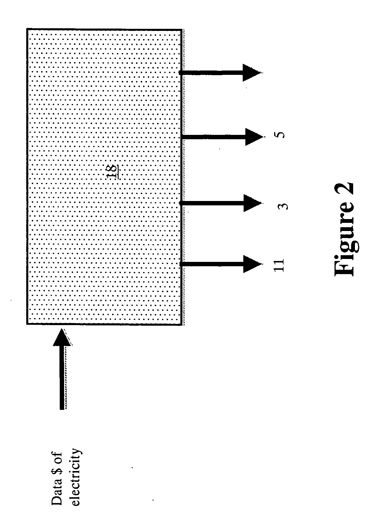
[0028]This invention is based on using an electrically pow...


PUM


Abstract

A method and apparatus are described for storing electrical power in the form of relative chemical potential between a concentrated solution, typically salt brine, and a dilute version of the same solution. To recover the power, the concentrated solution and dilute solution are supplied to a means for transforming the difference in their chemical potential into electrical power by such means as pressure retarded osmosis or reverse electrodialysis. In operation such means take in the concentrated and dilute solutions and exhaust a solution of intermediate concentration. The concentrated solution is supplied from a container such as a pond. It is generated by evaporation of the intermediate concentration solution in a second, separate pond, which receives the exhaust from the power generation means. The exhaust solution is concentrated by evaporation and is transferred into the first pond when the concentration has reached a sufficient level. To obtain a high evaporation rate in a relatively small evaporation area, the evaporation is enhanced to a rate faster than that obtained at the liquid surface of an open pond of the solution by employing electrical evaporation enhancement means. The electrical evaporation enhancement means is programmed to draw power from an electrical supply grid during periods when electricity demand is low and or when the cost of electricity is below or equal to an average cost over a period such as a diurnal cycle. When demand is high the enhancement is discontinued and the power generation means uses the stored concentrated brine to generate extra electrical power. Therefore the enhancement means would be used less than 30% of the time when the stored concentrated brine is being used to generate electrical power.

Description

CROSS-REFERENCE TO RELATED APPLICATIONS[0001]The present invention claims priority from U.S. Patent Application No. 61 / 239,112 filed Sep. 2, 2009, which is incorporated herein by reference for all purposes.FIELD OF THE INVENTION[0002]This invention relates to a method and system for storing energy during times when the cost of electricity is below or equal to an average cost or a first cost, and to utilizing the stored energy during times when electricity is above an average cost or the first cost; and more particularly to an automated system that provides a concentration difference between two solutions and utilizes that concentration difference to provide electricity in high demand periods.BACKGROUND OF THE INVENTION[0003]It is difficult to alter the supply of electricity from an electricity distribution grid to adapt to changes in local demand. One solution is to store energy locally during periods of low demand and use the stored energy to produce power during periods of high de...

Claims


Application Information

Patent Timeline
IPC IPC(8): H01M8/04H01M8/06
CPCH01M8/188Y02E60/50H01M14/00H01M8/227
Inventor MACDONALD, R. IANTEITELBAUM, NEIL
Owner MACDONALD R IAN
Why Eureka
Try Eureka