Belt monitoring system

a belt monitoring and belt width technology, applied in the direction of magnetic variables, instruments, transportation and packaging, etc., can solve the problem that the conveyor belt b>50/b> is the most susceptible to wear in the middle portion of the belt width, and achieve the effect of improving the monitoring accuracy and high accuracy

Active Publication Date: 2011-03-03
BRIDGESTONE CORP
View PDF6 Cites 80 Cited by
  • Summary
  • Abstract
  • Description
  • Claims
  • Application Information

AI Technical Summary

Benefits of technology

[0008]In a first aspect, the invention provides a belt monitoring system for detecting the condition of a conveyor belt, which comprises a transmitting sensor disposed on a conveyor belt for transmitting signals and a receiving sensor for receiving the signals from the transmitting sensor. The transmitting sensor includes a first transmitting sensor, which is embedded in a predetermined region in the belt width direction, and a second transmitting sensor, which is embedded in a predetermined position in the width direction of the conveyor belt. And the receiving sensor is a plurality of receiving sensors disposed at predetermined intervals in the belt width direction.
[0009]In a second aspect, the invention provides a belt monitoring system in which the first transmitting sensor and the second transmitting sensor are embedded a predetermined distance apart from each other in the circumferential direction of the conveyor belt.
[0010]In a third aspect, the invention provides a belt monitoring system in which the second transmitting sensor is embedded deeper than the first transmitting sensor.
[0011]In a fourth aspect, the invention provides a belt monitoring system in which the first transmitting sensor is a rubber magnet.
[0012]According to the present invention, a first transmitting sensor is embedded in a predetermined region in the width direction of a conveyor belt, and a second transmitting sensor is embedded in a predetermined position in the belt width direction. And a plurality of receiving sensors, which are arranged at predetermined intervals in the width direction of the conveyor belt, are disposed in a position apart from the surface of the conveyor belt. This arrangement makes it possible not only to detect the condition of the conveyor belt in the belt width direction using the signals from the first transmitting sensor but also to correct the detected condition of the conveyor belt for the effect of belt deviation by detecting the lateral deviation of the conveyor belt using the signals from the second transmitting sensor. Therefore, the condition of the conveyor belt can be monitored with high accuracy.
[0013]Also, the first transmitting sensor and the second transmitting sensor may be embedded a predetermined distance apart from each other in the circumferential direction of the conveyor belt. This will separate the signals from the first transmitting sensor and the signals from the second transmitting sensor clearly from each other, so that the accuracy of monitoring can be further improved.

Problems solved by technology

Also, the conveyor belt 50 is most susceptible to wear in the middle portion of the belt width where the loads are placed.

Method used


Image

  • Belt monitoring system
  • Belt monitoring system
  • Belt monitoring system

Examples


Embodiment Construction

[0040]The best mode (preferred embodiments) of the present invention will be described hereinbelow with reference to the accompanying drawings.

[0041]The following description of the preferred embodiments relates to a case of monitoring the distribution of belt thickness in the belt width direction which results from the wear of the conveyor belt.

[0042]FIGS. 1 to 5 illustrate the best mode for carrying out invention.

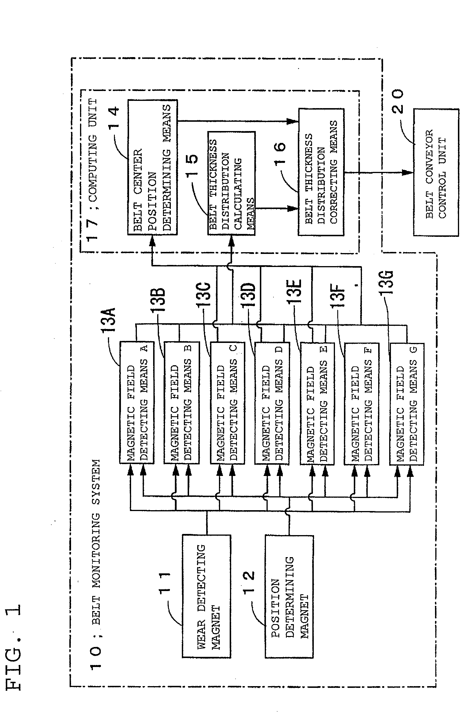
[0043]FIG. 1 is a functional block diagram of a monitoring system 10 according to the present invention.

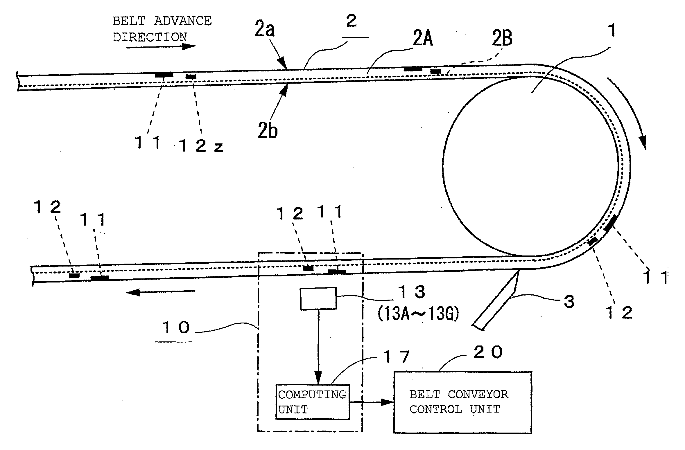
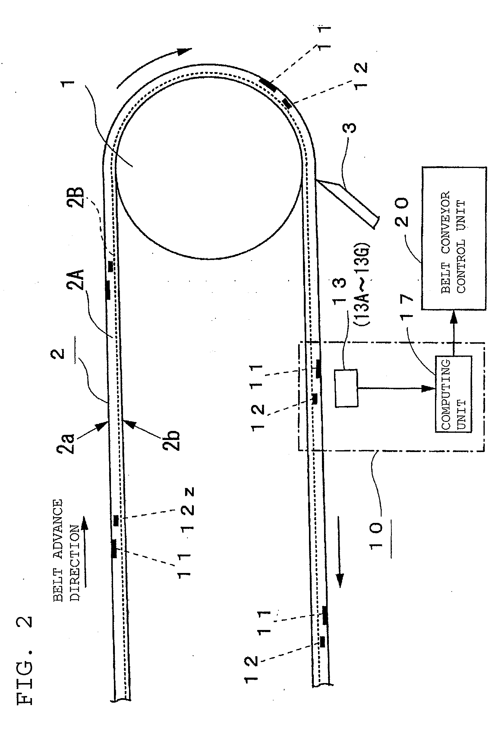
[0044]FIG. 2 is a side view of the unloading end of a belt conveyor system.

[0045]FIG. 3 is a sectional view showing where the rubber magnets are embedded in a conveyor belt 2.

[0046]FIG. 4 is a feature plan view of a conveyor belt 2 seen from the measuring unit side.

[0047]FIG. 5 is an illustration of a return-side straight-run portion of a conveyor belt 2, showing a case where a position determining and cycle reference position determining magnet 12z is located in a retu...


PUM


Abstract

A belt monitoring system which can accurately monitor the condition of a conveyor belt by correcting it for the effect of belt deviation. Wear detecting magnets (11), which are rubber magnets spanning the entire belt width, are embedded at intervals along the circumferential direction of the conveyor belt (2). Also, position determining magnets (12, 12z) are embedded in positions a predetermined distance apart from the wear detecting magnets (11). In addition, a plurality of magnetic field detecting means (13: 13A-13G) for detecting the magnetic fields from the magnets (11, 12, 12z), which are arranged at predetermined intervals in the width direction of the conveyor belt (2), are disposed in a position spaced apart from the surface of the conveyor belt (2). The state of deviation of the conveyor belt (2) is detected based on the output signals from the position determining magnets (12, 12z) detected by the magnetic field detection means (13), and then the belt thickness distribution of the conveyor belt (2) in the width direction is corrected based on the detected state of belt deviation.

Description

TECHNICAL FIELD[0001]The present invention relates to a belt monitoring system capable of accurately monitoring the condition, such as belt thickness distribution, of a conveyor belt.BACKGROUND ART[0002]Conventional methods for detecting the wear status of a conveyor belt or a feed belt have been such that, as shown in FIGS. 8A and 8B, a rubber magnet 51, which is magnetized in the thickness direction of a conveyor belt 50, is embedded between the surface 50a of a rubber member 50A of a conveyor belt 50 and a reinforcement member 50B provided on the rear surface 50b side of the conveyor belt 50, and also a magnetic sensor 52, which detects changes in the magnetic field from the rubber magnet 51, is disposed in a location where the rubber magnet 51 passes by. And the depth of wear of the conveyor belt 50 is calculated from the magnitude of magnetic field detected by this arrangement. Also, as shown in FIG. 8C, a belt deviation detecting means 54 is disposed in a position lateral to a...

Claims


Application Information

Patent Timeline
Patent Type & Authority Applications(United States)
IPC IPC(8): G01R33/12
CPCB65G43/04B65G43/02
Inventor FURUKAWA, KAZUYA
Owner BRIDGESTONE CORP
Why Eureka
Try Eureka