Device housing

a technology for devices and housings, applied in the direction of antenna details, elongated active element feeds, antennas, etc., can solve the problems of difficult printing of conductive ink coatings on the housings, prone to damage of three-dimensional antennas mounted without a support member,

Inactive Publication Date: 2011-03-03
SHENZHEN FUTAIHONG PRECISION IND CO LTD +1
View PDF5 Cites 7 Cited by
  • Summary
  • Abstract
  • Description
  • Claims
  • Application Information

AI Technical Summary

Problems solved by technology

However, the antenna, especially the three-dimensional antenna mounted without a support member is prone to be damaged during manufacturing.
However, the conductive ink coating

Method used


Image

  • Device housing
  • Device housing
  • Device housing

Examples


Embodiment Construction

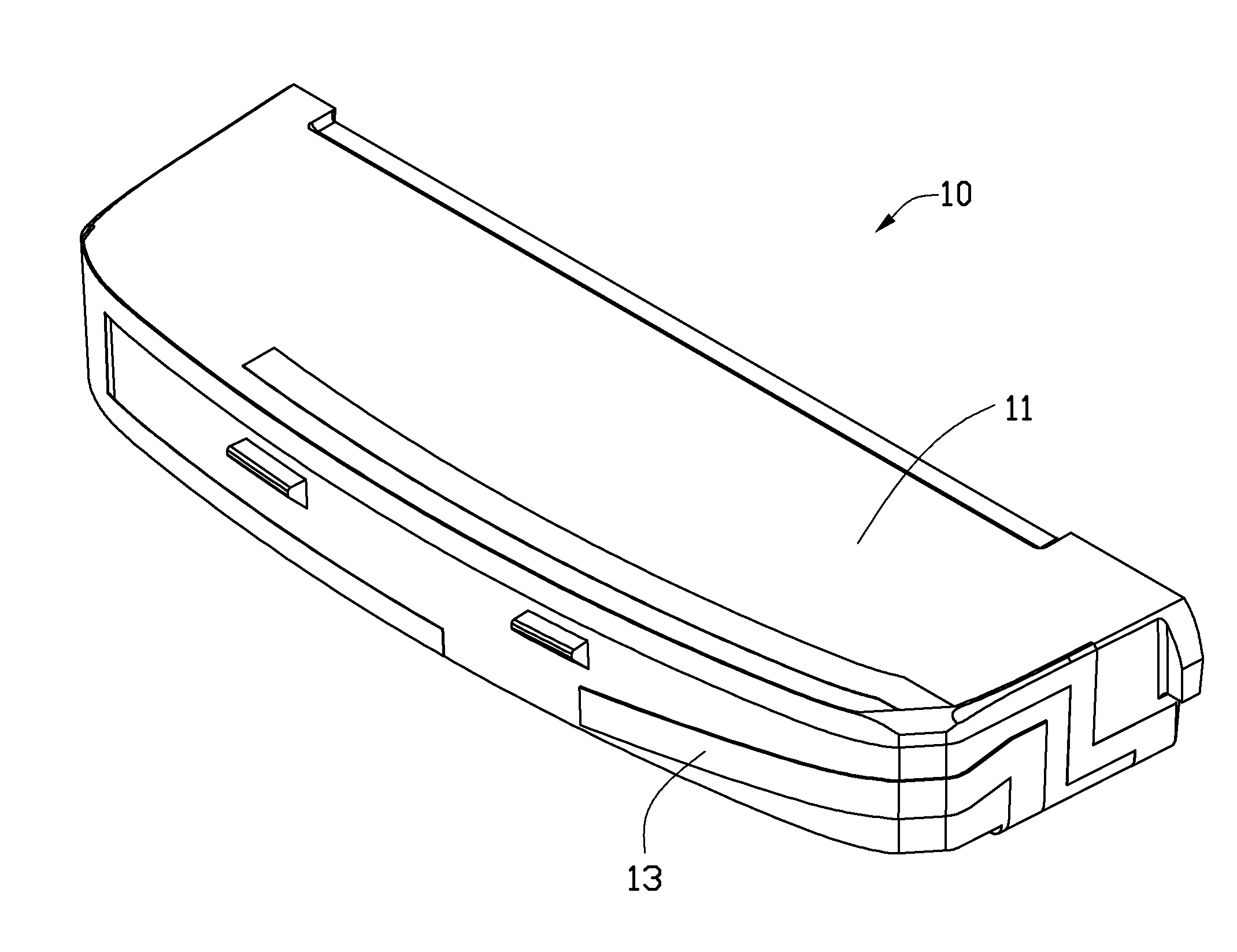
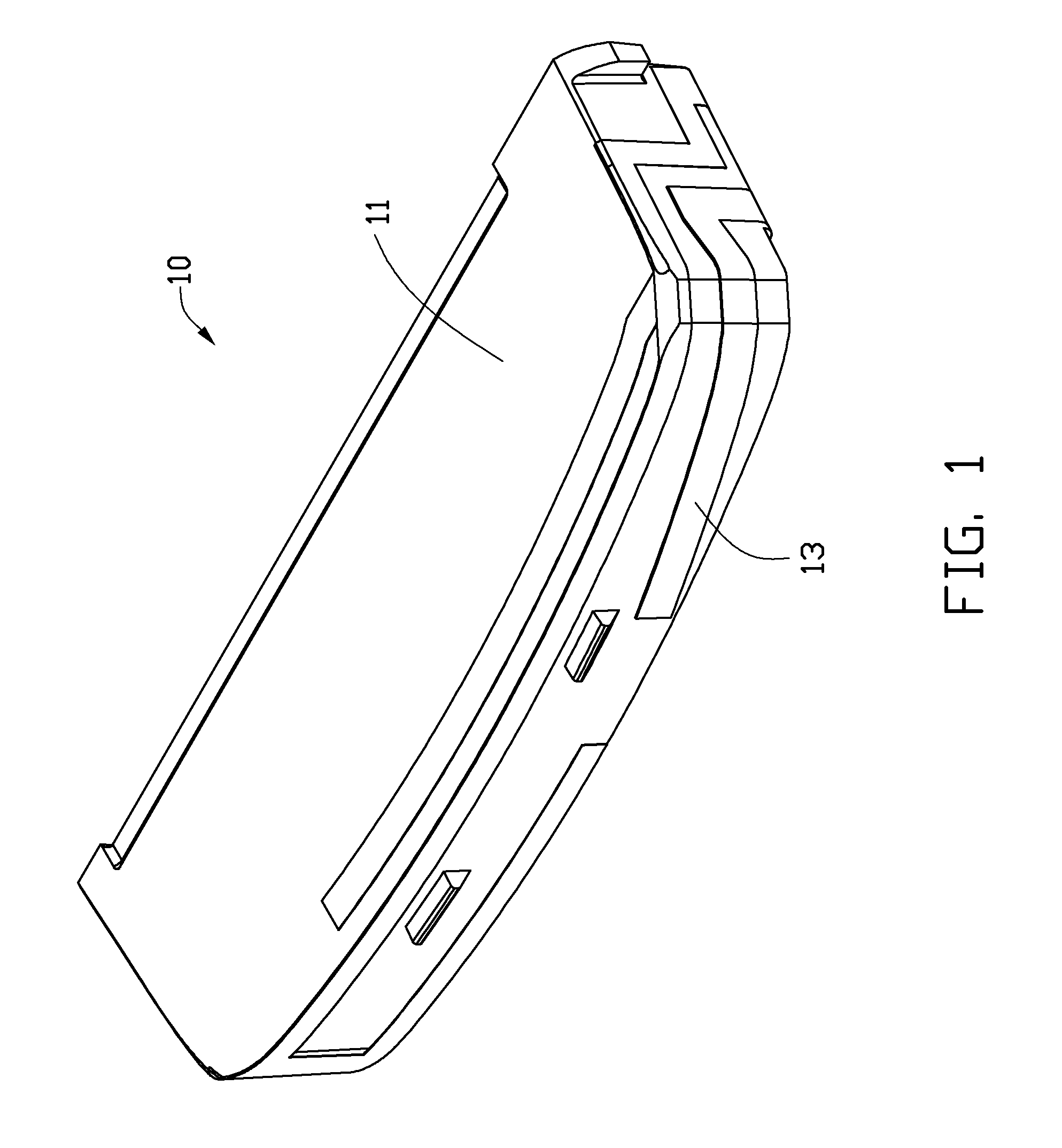
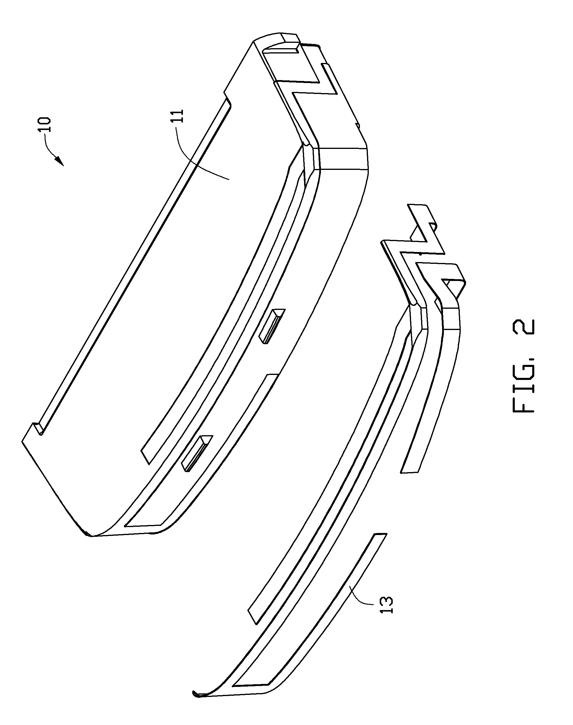
FIG. 1 shows a device housing 10 including a main body 11 and a three-dimensional antenna 13 formed on the main body 11. By three-dimensional, it is meant that the antenna is not confined to one plane in shape. The main body 11 and the three-dimensional antenna 13 are formed by a two-shot injection molding process.

The main body 11 may be molded with non-conductive plastics. The non-conductive plastics may be one or more materials selected from a group consisting of polypropylene (PP), polyamide (PA), polycarbonate (PC), polyethylene terephthalate (PET), and polymethyl methacrylate (PMMA).

The three-dimensional antenna 13 may be molded directly on the main body 11 using conductive plastic. The three-dimensional antenna 13 may define electrical contacts thereon (not shown in the figure).

The conductive plastics for forming the three-dimensional antenna 13 may be conductive fiber enhancing plastics. The conductive fiber enhancing plastic is manufactured from thermoplastic material compos...


PUM


Abstract

A device housing comprises a main body and an three-dimensional antenna formed on the main body. The main body is made of non-conductive plastic. The three-dimensional antenna is made of conductive plastic. The main body and the three-dimensional antenna are formed by a two-shot injection molding process.

Description

BACKGROUND1. Technical FieldThe present disclosure relates to device housings, especially to a device housing having a three-dimensional antenna formed thereon.2. Description of Related ArtAntennas are critical for wireless communication of electronic devices. The antenna may be a thin metal piece mounted to a support member, and attached to a device's housing. To save space, weight, and money, the antenna may be directly attached to the housing without the support member. However, the antenna, especially the three-dimensional antenna mounted without a support member is prone to be damaged during manufacturing. To solve this problem, a printable antenna is used by printing conductive ink coatings on the housings. However, the conductive ink coatings can be difficult to print on the housings especially when trying to form three-dimensional antennas, which perform better in some applications than two-dimensional antennas.Therefore, there is room for improvement within the art.BRIEF DE...

Claims


Application Information

Patent Timeline
IPC IPC(8): H01Q1/24
CPCH01Q1/243H01Q9/42H01Q1/38
Inventor WANG, QIANG
Owner SHENZHEN FUTAIHONG PRECISION IND CO LTD
Why Eureka
Try Eureka