Liquid ejection apparatus and non-transitory storage medium storing program

Active Publication Date: 2011-03-03
BROTHER KOGYO KK
View PDF4 Cites 14 Cited by
  • Summary
  • Abstract
  • Description
  • Claims
  • Application Information

AI Technical Summary

Benefits of technology

[0008]This invention has been developed in view of the above-described situations, and it is an object of the present invention to provide a liquid ejection apparatus which makes a flushing dot inconspicuous.
[0009]The object indicated above may be achieved according to the present invention which provides a liquid ejection apparatus comprising: a feeding mechanism configured to feed a recording medium in a feeding direction; a first ejection head having a first liquid-ejection opening through which is ejected first liquid that is for forming an image on the recording medium; a second ejection head having a second liquid-ejection opening through which is ejected second liquid that is liquid to be ejected on the recording medium to reduce a degree of absorption of the first liquid into the recording medium; an image-data storage section configured to store image data of the image to be recorded on the recording medium; an image-recording controlling section configured to control the first ejection head on the basis of the image data stored in the image-data storage section such that an image dot is to be formed on the recording medium by the first liquid ejected from the first liquid-ejection opening of the first ejection head and landed on the recording medium; a flushing-operation-data producing section configured to produce flushing-operation data for a flushing operation of the first liquid; a flushing-operation controlling section configured to control the first ejection head on the basis of the flushing-op

Problems solved by technology

However, in the printer using the treatment liquid as described above, there is a risk that the treatment liquid sharpens not only the dot for forming the image but also the flushing

Method used


Image

  • Liquid ejection apparatus and non-transitory storage medium storing program
  • Liquid ejection apparatus and non-transitory storage medium storing program
  • Liquid ejection apparatus and non-transitory storage medium storing program

Examples


Example

[0022]Hereinafter, there will be described an embodiment of the present invention by reference to the drawings.

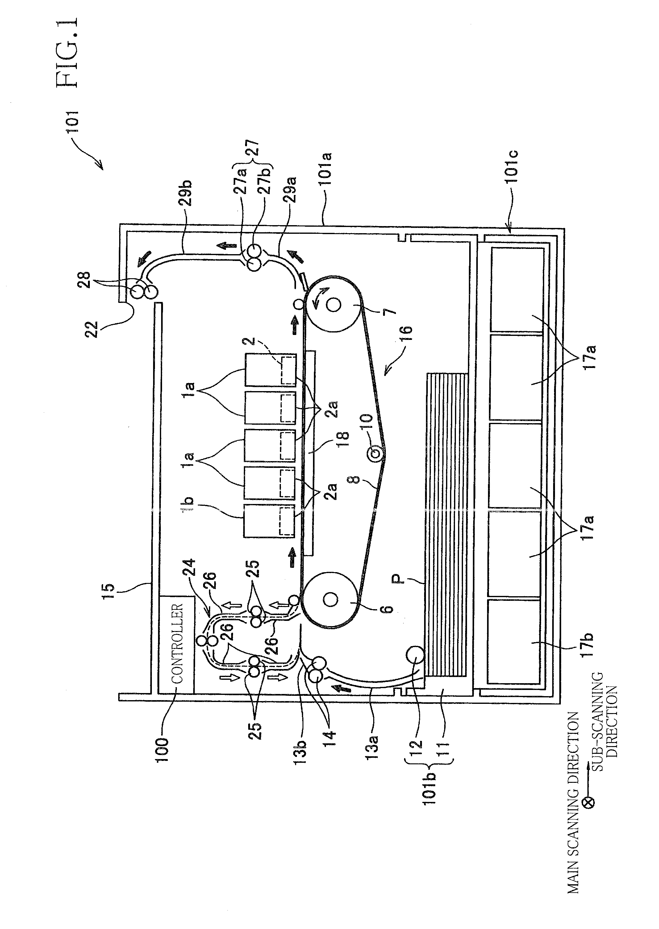
[0023]As shown in FIG. 1, an ink jet printer 101 as a present embodiment includes a casing 101a having a rectangular parallelepiped shape. In the casing 101a, there are provided (a) a sheet feeding mechanism 16 configured to feed a sheet P as a recording medium in a forward sheet feeding direction which is a rightward direction in FIG. 1 or in a reverse sheet feeding direction which is opposite or reverse to the forward sheet feeding direction and (b) four recording heads 1a as first ejection heads and a treatment-liquid ejection head 1b as a second ejection head disposed on an upper side of the sheet feeding mechanism 16. The four recording heads 1a respectively eject ink (first liquid) of four colors, namely, cyan, magenta, yellow, and black, onto the sheet P fed in the forward sheet feeding direction by the sheet feeding mechanism 16 (that is, the forward sheet feeding d...


PUM


Abstract

A liquid ejection apparatus including: a flushing-operation-data producing section which produces flushing-operation data for flashing of ink; a second-liquid-ejection-data producing section which produces data about ejection of treatment liquid such that (i) the treatment liquid is to be landed on a dot area on which the ink is to be landed upon forming an image dot among dot areas and (ii) an amount of the treatment liquid landed to be on at least one dot area on which the ink is to be landed upon flashing of the ink is made smaller, by referring the flushing-operation data produced by the flushing-operation-data producing section, than an amount of the treatment liquid to be landed on a dot area on which the ink is not to be landed upon flashing; and a second-liquid controlling section which controls a head on the basis of the data produced by the second-liquid-ejection-data producing section.

Description

CROSS REFERENCE TO RELATED APPLICATION[0001]The present application claims priority from Japanese Patent Application No. 2009-195794, which was filed on Aug. 26, 2009, the disclosure of which is herein incorporated by reference in its entirety.BACKGROUND OF THE INVENTION[0002]1. Field of the Invention[0003]The present invention relates to a liquid ejection apparatus including (a) a recording head configured to form image dots and flushing dots on a recording medium by ejecting ink droplets onto the recording medium and (b) a treatment-liquid ejection head configured to eject droplets of the treatment liquid.[0004]2. Description of the Related Art[0005]In general, an ink-jet printer including an ink-jet head configured to eject ink droplets from a plurality of liquid-ejection openings performs a preliminary ejection (i.e., flushing) for ejecting ink whose viscosity has been increased, in addition to a normal ejection for ejecting the ink droplets to form an image, in order to prevent...

Claims


Application Information

Patent Timeline
IPC IPC(8): B41J29/38
CPCB41J2/2114B41J2/16526
Inventor ITOGAWA, YOSHIHIRO
Owner BROTHER KOGYO KK
Why Eureka
Try Eureka