Fundus camera

a camera and fundus technology, applied in the field offundus cameras, can solve the problems of blurred fundus image, out-of-focus image, and focus of some examined eyes, and achieve the effect of easy alignmen

Inactive Publication Date: 2011-03-03
CANON KK
View PDF5 Cites 33 Cited by
  • Summary
  • Abstract
  • Description
  • Claims
  • Application Information

AI Technical Summary

Benefits of technology

[0013]The present invention is directed to prov

Problems solved by technology

Therefore, when there are personal differences in aberration in the examined eye's optical system, if an image is captured only based on the focus split index image positions which are predetermined, there is a possibility that errors may occur in focusing for some examined eyes, resulting in a blurred fundus

Method used


Image

  • Fundus camera
  • Fundus camera
  • Fundus camera

Examples


fourth embodiment

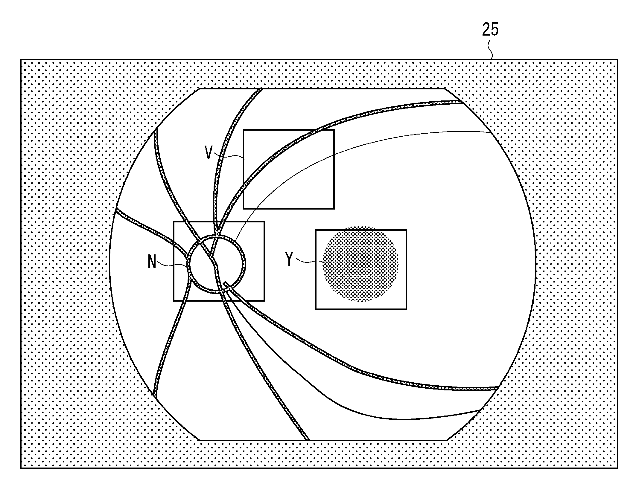
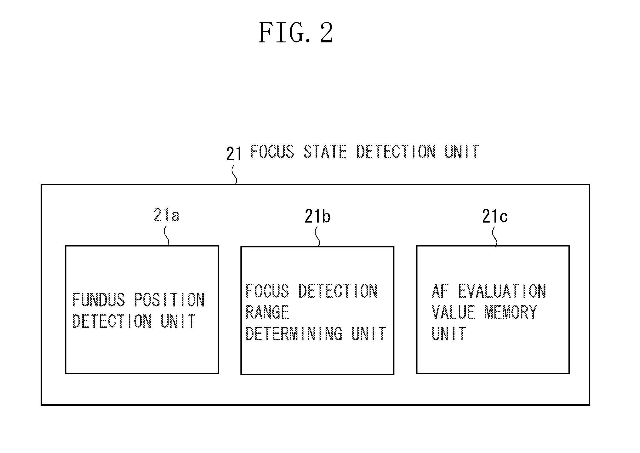
[0069]In the fourth embodiment, the focus state detecting unit 21 calculates AF evaluation values for a plurality of fundus image specific regions of a fundus image extracted by the fundus position detecting unit 21a. The focus state detecting unit 21 can obtain images focused evenly at a plurality of regions extracted by pattern recognition by using a total value of the AF evaluation values as an overall evaluation value, and by detecting a maximum value of the overall evaluation value.

[0070]In the fourth embodiment, as illustrated in FIG. 10, the focus detection range determining unit 21b includes a focus detection range limiting unit 21g. The focus detection range limiting unit 21g automatically determines, as a focus detection range, one region with a highest AF evaluation value from among the specific regions of the fundus image extracted by the fundus position detecting unit 21a, and sends the focus detection range to the focus state detecting unit 21. The selected specific re...

fifth embodiment

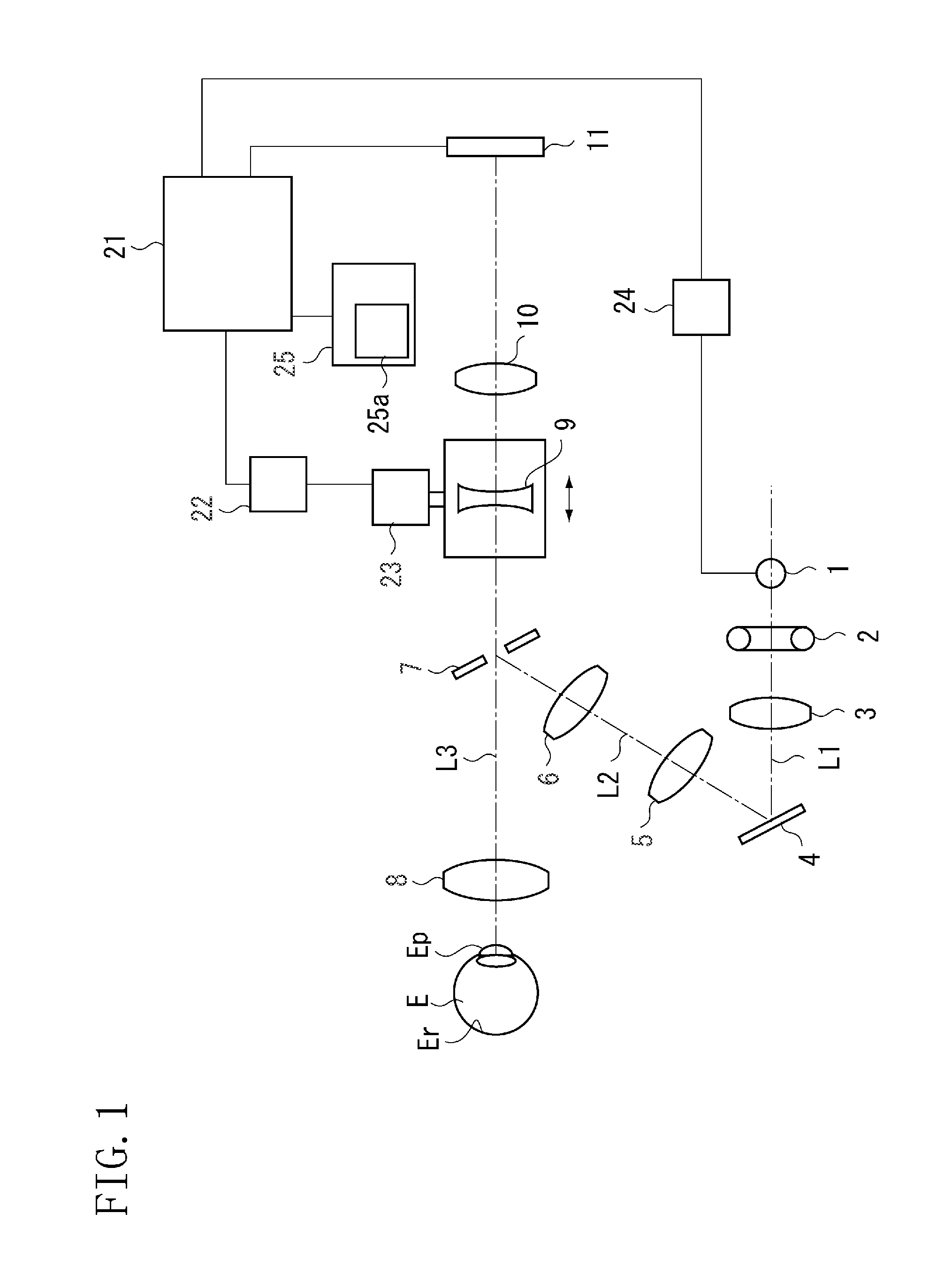
[0073]FIG. 11 is an external view of a fundus camera in which a table 32, movable in the back-forth and left-right directions as indicated by arrows, is mounted on a pedestal 31. A housing 33 containing an optical system of a fundus camera illustrated in FIG. 1, a display monitor 25, and an operation bar 35 fitted with a shooting button 34 are mounted on the table 25.

[0074]The examiner operates the operation bar 35, and adjusts the table 32 in the left / right direction on a horizontal plane to match the left and right eyes of a subject. Since a left / right eye detecting unit 36 is disposed between the pedestal 31 and the table 32, the left-right position of the housing 33 can be detected, so that it is known which of the subject's examined eyes E is being observed and photographed.

[0075]FIG. 12 is a diagram illustrating a detection method by the left / right eye detecting unit 36. A low portion 31a and a high portion 31b, showing a height difference, are formed on the upper surface of ...


PUM


Abstract

When pattern recognition of a fundus image is started in step S1, output from a fundus image sensing unit is compared with a regional pattern of stored fundus image specific regions in step S2, and it is decided whether to proceed to pattern recognition. If pattern recognition is possible, based on an AF evaluation value, the lens is driven, with which automatic focusing is completed.

Description

BACKGROUND OF THE INVENTION[0001]1. Field of the Invention[0002]The present invention relates to a fundus camera to take an image of a fundus of a subject's eye for use, for example, in ophthalmic hospitals and mass medical examination.[0003]2. Description of the Related Art[0004]It is well known that to facilitate focusing on a fundus of a subject's eye, images of indexes are projected to the fundus, and a positional relation of index images is observed through a focusing lens of an observing and photographing system, to thereby obtain a clear image of the fundus.[0005]Japanese Patent Application Laid-Open No. 5-95907 discusses a fundus camera, in which two focus split index images projected onto the fundus are captured and a focus state is detected based on positions of the focus split index images while attenuating the brightness of the index images.[0006]Japanese Patent Application Laid-Open No. 8-275921 discusses an ophthalmic apparatus, in which focus index images are projecte...

Claims


Application Information

Patent Timeline
IPC IPC(8): A61B3/14
CPCA61B3/12G03B3/10G06T2207/30041G06T7/0044G03B13/36G06T7/74
Inventor INOUE, HIROYUKITANAKA, SHINYAAOKI, HIROSHI
Owner CANON KK
Why Eureka
Try Eureka