

Imaging optical system, camera and personal digital assistant
a technology of optical system and optical filter, applied in the direction of exposure control, camera filters, instruments, etc., can solve the problems of large diameter nd filter, large shutter unit size, and increased power consumption, so as to effectively reduce or prevent the generation of ghost images
- Summary
- Abstract
- Description
- Claims
- Application Information
AI Technical Summary
Benefits of technology
Problems solved by technology
Method used
Image

Examples
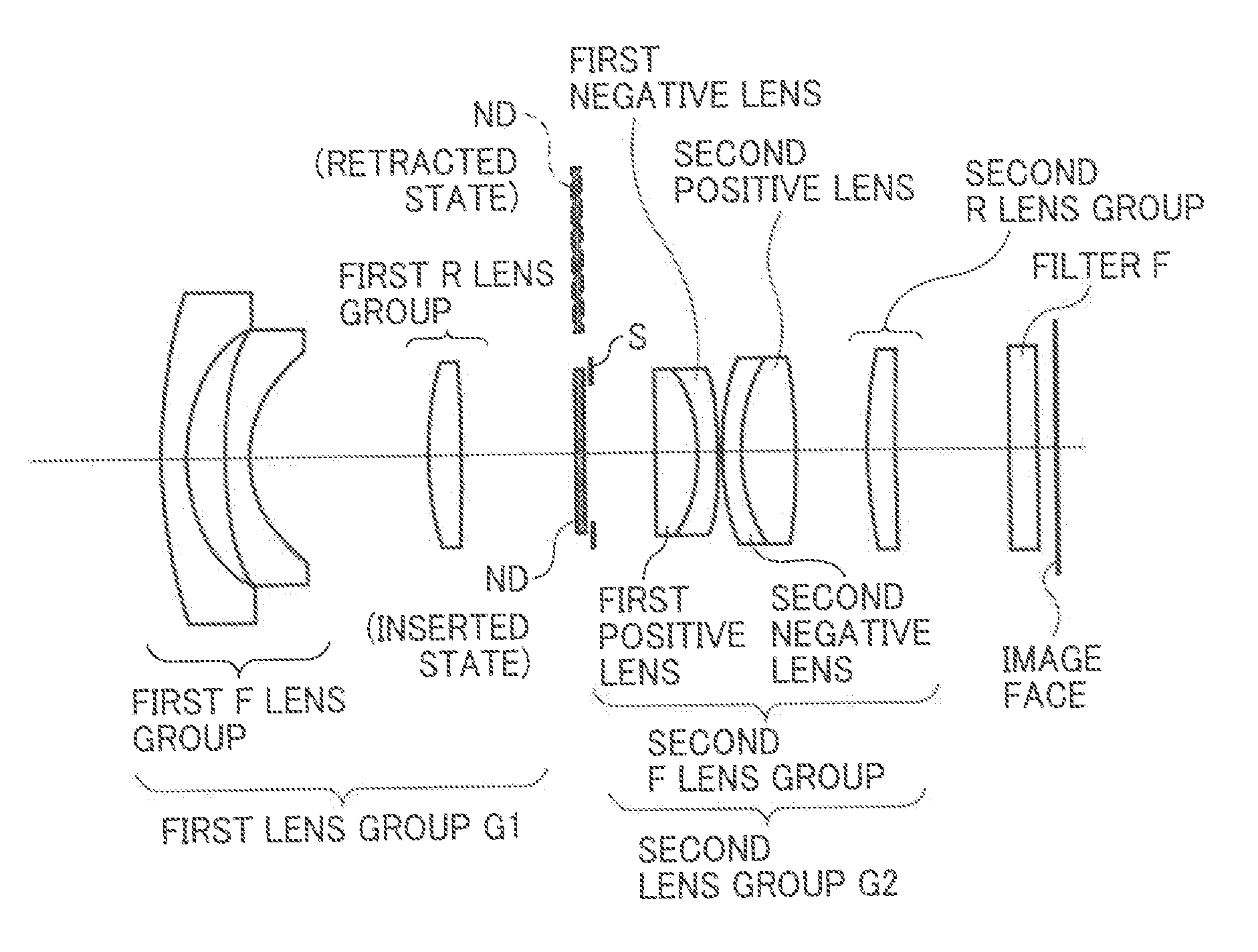
embodiment 1
[0068]Table 1 illustrates data of each lens and filter according to Embodiment 1.
TABLE 1Embodiment 1focal length 6.00half-field angle 39.09Fno 1.96SURFACEGLASSNUMBERRDNνTYPEREMARKS125.0261.21.49781.54S-FPL51FIRST LENSFIRST LENS282.27GROUP317.51.21.5163364.06L-BSL7SECOND LENS45.0739.62518.2091.711.8348142.71S-LAH55THIRD LENS6−88.5196.77∞3.5——APERTURE STOP8∞2.271.49781.54S-FPL51FOURTH LENSSECOND LENS9−7.55911.7215129.23S-TIH18FIFTH LENSGROUP10−20.6370.21112.82611.6541239.68S-NBH5SIXTH LENS128.3413.031.49781.54S-FPL51SEVENTH LENS13−26.3013.651418.1251.51.5163364.06L-BSL7EIGHTH LENS15160.3566.0716∞1.51.5489269.31FILTER17∞
[0069]“Aspherical Lens Shape Data”
[0070]Table 2 illustrates the data of the aspherical lens shape.
TABLE 2Aspherical SurfaceKA2A4A6A84−0.40−3.8568E−04−8.2523E−06−1.1521E−07A10A12A14A16A184−2.5946E−09−2.7651E−11−1.2444E−132.3642E−15−1.1047E−15KA2A4A6A8A101400−2.9359E−042.2462E−06−1.6205E−072.3075E−09
[0071]In the above aspherical surface marks, for example, “2.3075E-09” me...
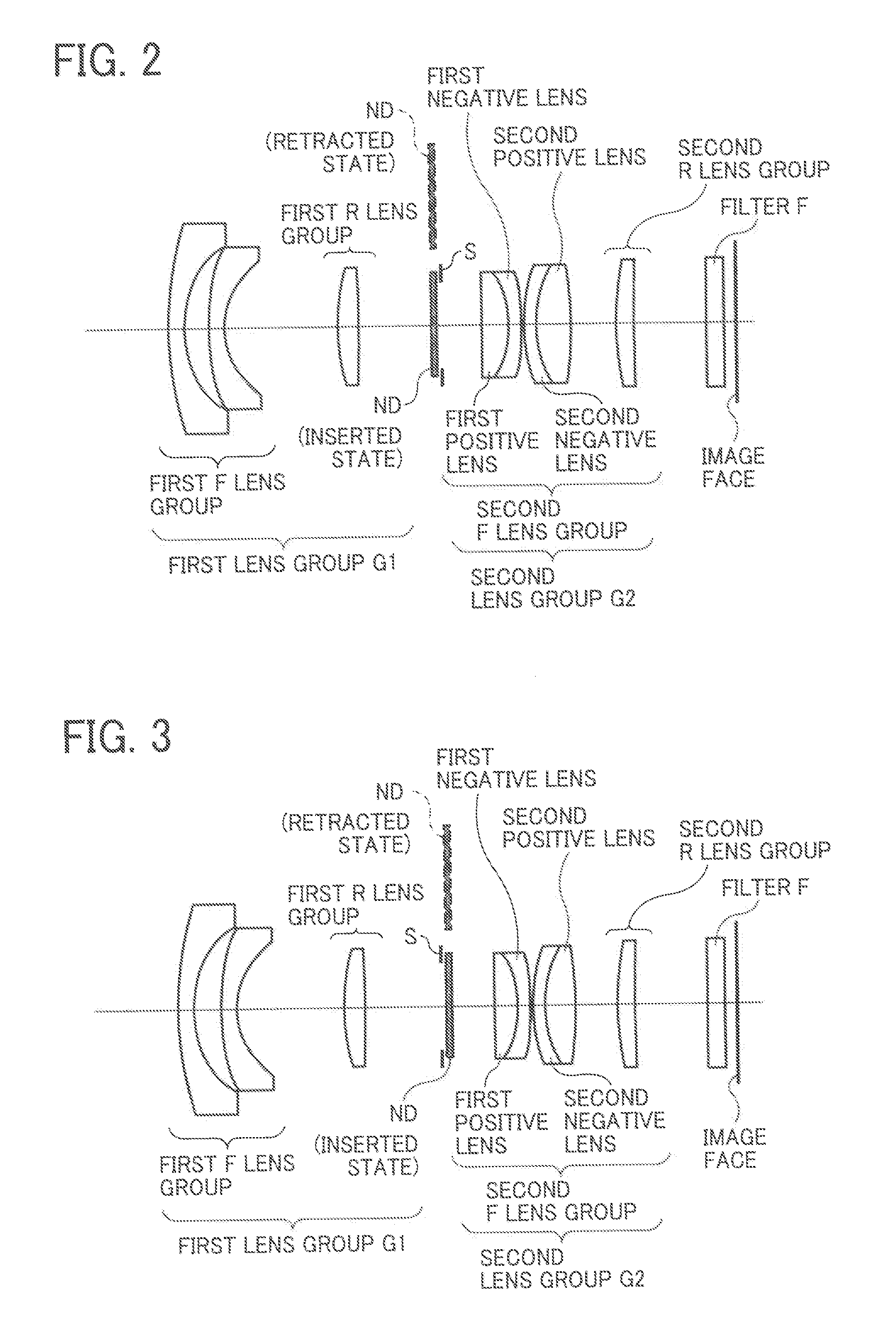
embodiment 2
[0074]Table 4 illustrates data of each lens and filter according to Embodiment 2.
TABLE 4Embodiment 2focal length 6.00half-field angle 39.12°Fno 1.95SURFACEGLASSNUMBERRDNdνdTYPEREMARKS125.961.21.4874970.24S-FSL5FIRST LENSFIRST F LENS27.22.51GROUP3151.21.5163364.06L-BSL7SECOND LENS44.9268.83518.3571.761.80446.57S-LAH65THIRD LENSFIRST R LENS6−46.6546.22GROUP7∞4.26——APERTURE STOP8115.0691.991.49781.54S-FPL51FOURTH LENSSECOND F LENS9−8.311.7407727.79S-TIH13FIFTH LENSGROUP10−21.6350.21112.47311.7204734.71S-NBH8SIXTH LENS128.4332.511.49781.54S-FPL51SEVENTH LENS13−33.1863.41416.8921.51.5163364.06L-BSL7EIGHTH LENSSECOND R LENS15108.715.73GROUP16∞1.51.5489269.31FILTER17∞
[0075]“Aspherical Lens Shape Data”
[0076]Table 5 illustrates aspherical lens shape data.
TABLE 5Aspherical SurfaceKA2A4A6A8A104−0.8945506.6197E−05−2.2678E−06−9.2764E−08−1.0794E−09KA2A4A6A8A101400−3.1109E−042.2882E−06−1.4584E−071.8406E−09
[0077]“Parameter Value of Conditional Expression”
[0078]Table 6 illustrates parameter values o...
PUM
 Abstract
Description
Claims
Application Information