
Spline Shaft Assembly

Inactive Publication Date: 2011-03-03
WANG SHENG HUI
View PDF7 Cites 8 Cited by
  • Summary
  • Abstract
  • Description
  • Claims
  • Application Information

AI Technical Summary

Benefits of technology

[0010]The spline shaft assembly of the present invention is easier to construct compared to the conventional spline shaft assemblies.

Problems solved by technology

However, the broaching machine is expensive, and the cutting amount thereof per unit time is relatively small (approximately 0.02 mm).
As such, the rotatable shaft 11 must be machined to engage fittingly the grooves 12, which results in a troublesome manufacturing process for the conventional spline shaft assembly 1.
Once the rotatable shaft 11 and the grooves 12 of the transmission member 12 do not engage fittingly, unwanted noise and vibration will be generated to thereby reduce the operating efficiency of the conventional spline shaft assembly 1.
The configuration of the ball-bearing spline shaft 3 is complicated and the installation of the ball-bearing spline shaft 3 is cumbersome.

Method used


Image

  • Spline Shaft Assembly
  • Spline Shaft Assembly
  • Spline Shaft Assembly

Examples


Embodiment Construction

[0020]Before the present invention is described in greater detail, it should be noted that like elements are denoted by the same reference numerals throughout the disclosure.

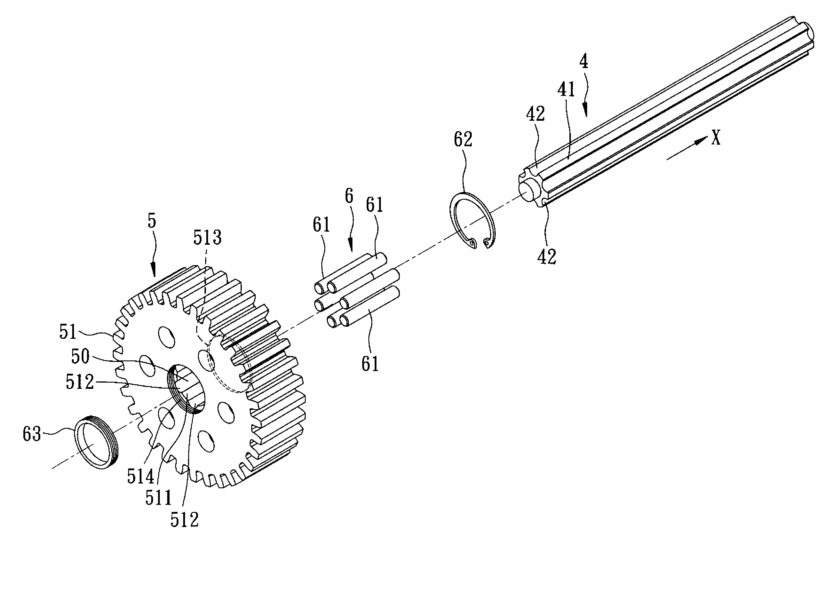
[0021]As shown in FIGS. 4 and 5, a first preferred embodiment of a spline shaft assembly according to the present invention comprises a rotatable shaft 4, a transmission module 5, and a spline key set 6.

[0022]The rotatable shaft 4 extends along an axial direction (X), and has an outer surface 41, and a plurality of first grooves 42 formed in the outer surface 41. Each of the first grooves 42 is defined by a semi-circular groove-defining wall 420.

[0023]The transmission module 5 has a transmission member 51 configured as a spur gear in this embodiment. The transmission member 51 is formed with a through hole 50, and has an inner surface 511 defining the through hole 50, and a plurality of axially extending second grooves 512 formed in the inner surface 511. Each of the second grooves 512 is defined by a semi-circu...


PUM


Abstract

A spline shaft assembly includes a rotatable shaft extending along an axial direction and having an outer surface, and a plurality of first grooves formed in the outer surface. A transmission module is formed with a through hole and has an inner surface defining the through hole, and a plurality of axially extending second grooves formed in the inner surface. Each of the first and second grooves is defined by a semi-circular groove-defining wall. The rotatable shaft extends through the through hole. A spline key set has a plurality of cylindrical keys extending along the axial direction and disposed between and engaging the first grooves and the second grooves, and at least two positioning members connected to the transmission module and associated with the cylindrical keys such that the transmission module and the cylindrical keys are co-rotatable.

Description

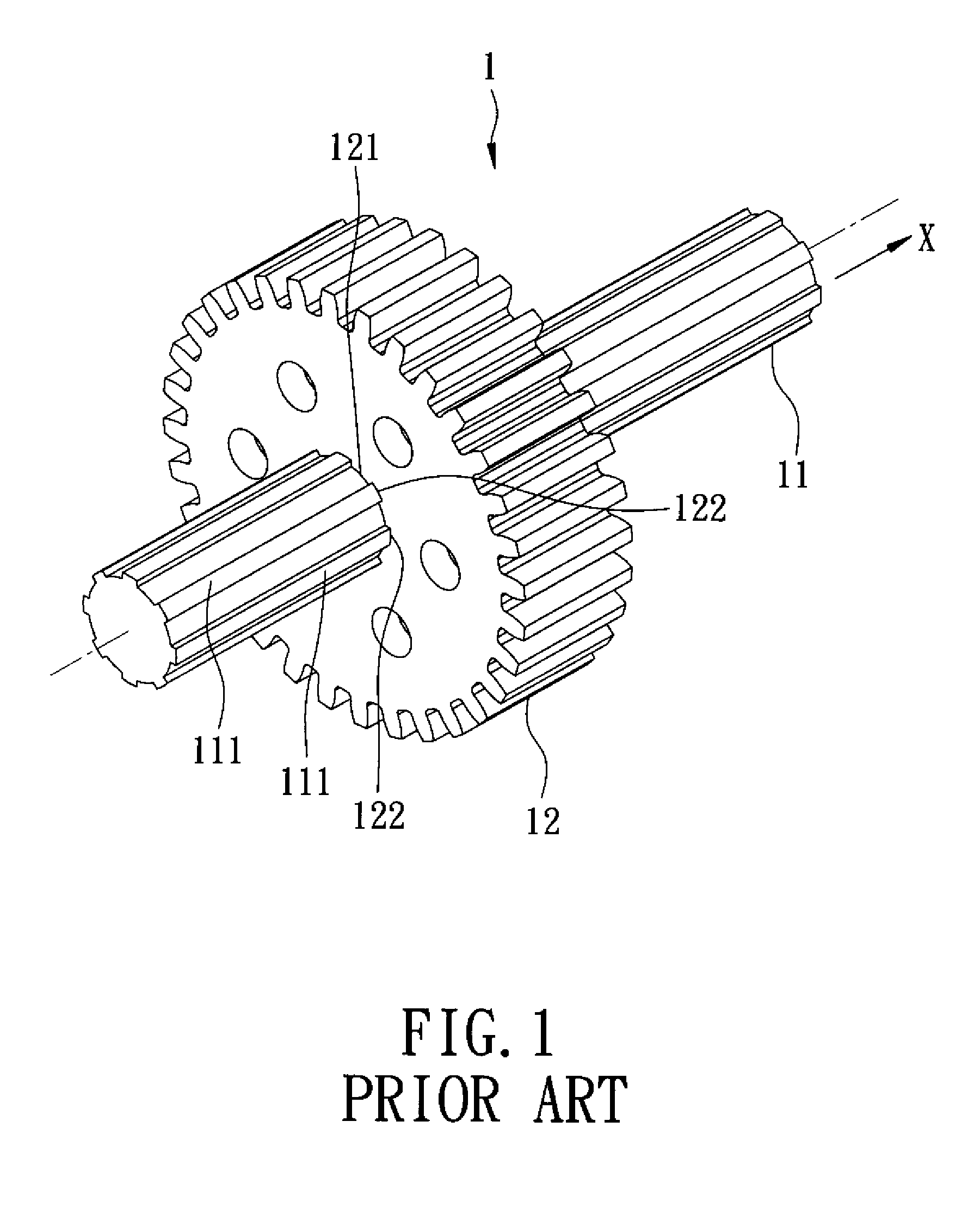
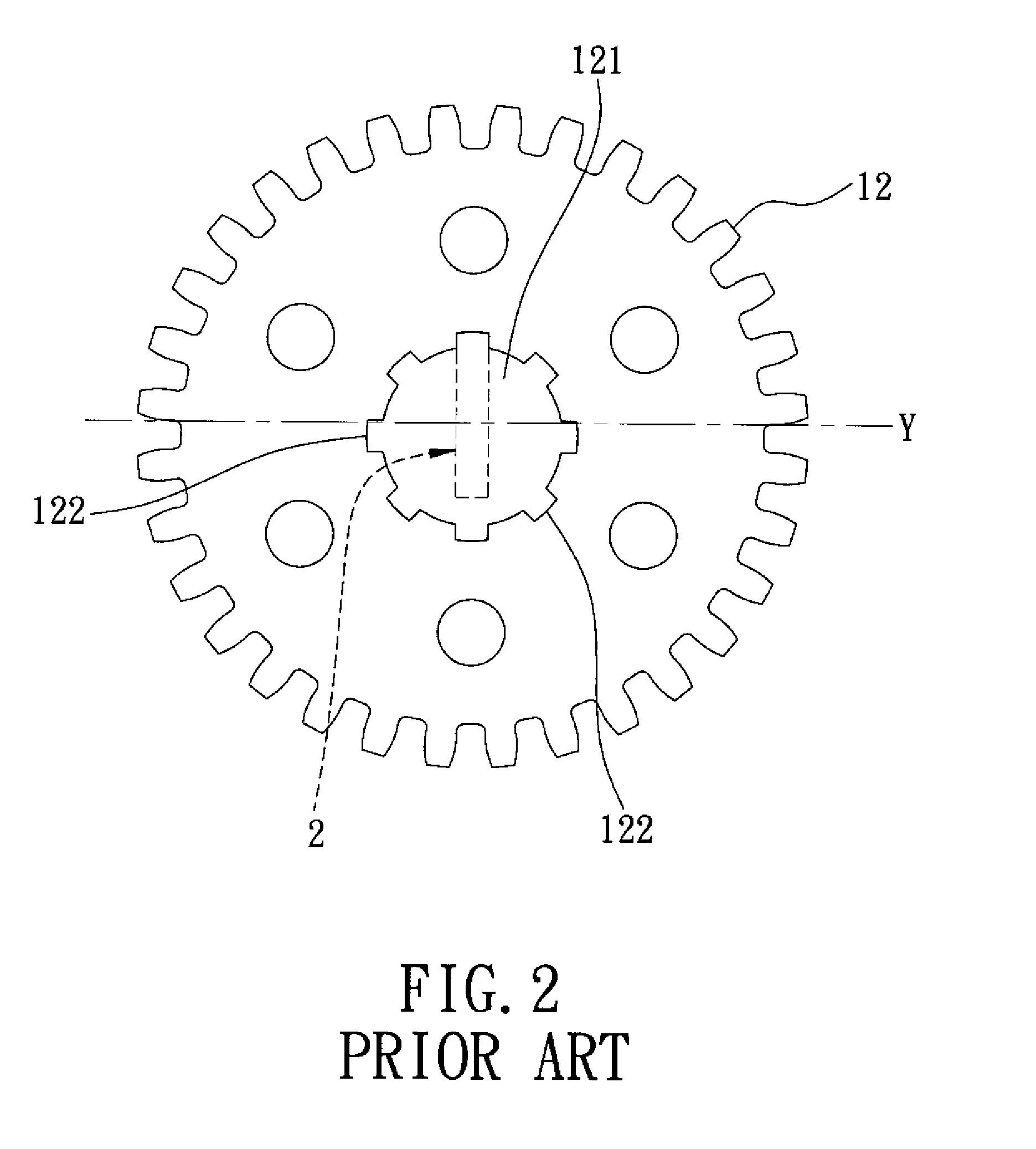
BACKGROUND OF THE INVENTION[0001]1. Field of the Invention[0002]The invention relates to a spline shaft, more particularly to a spline shaft assembly capable of transmitting torque.[0003]2. Description of the Related Art[0004]Referring to FIGS. 1 and 2, a conventional spline shaft assembly 1 comprises a rotatable shaft 11 extending along an axial direction (X), and a transmission member 12 configured as a spur gear. The rotatable shaft 11 has an outer surface and a plurality of keys 111 formed in the outer surface of the rotatable shaft 11. The transmission member 12 is formed with a through hole 121 and has an inner surface defining the through hole 121, and a plurality of axially extending grooves 122 formed in the inner surface of the transmission member 12. The rotatable shaft 11 extends through the through hole 121. The keys 111 of the rotatable shaft 11 engage respectively the grooves 122 of the transmission member 12 such that the rotatable shaft 11 and the transmission membe...

Claims


Application Information

Patent Timeline
IPC IPC(8): F16D3/06
CPCY10T403/7021F16D3/06
Inventor CHEN, FENG-TIEN
Owner WANG SHENG HUI
Learn More