Magnetic boot attachment for a stirrup

Inactive Publication Date: 2011-03-10
ONTYTE
View PDF23 Cites 10 Cited by
  • Summary
  • Abstract
  • Description
  • Claims
  • Application Information

AI Technical Summary

Problems solved by technology

Such restraints usually require assistance to put on, are unsightly in competiti

Method used


Image

  • Magnetic boot attachment for a stirrup
  • Magnetic boot attachment for a stirrup
  • Magnetic boot attachment for a stirrup

Examples


Embodiment Construction

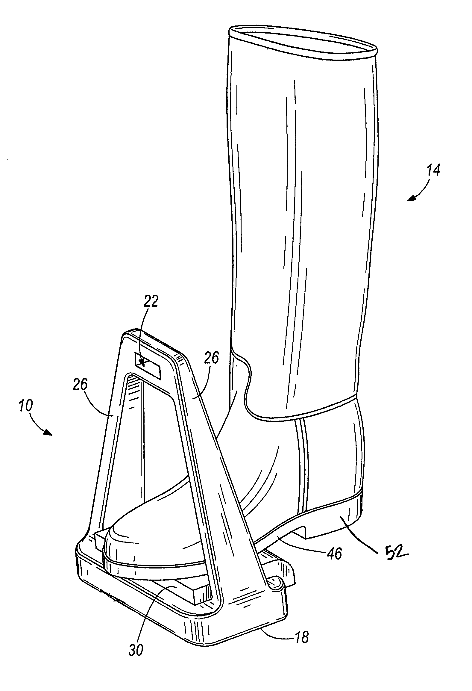
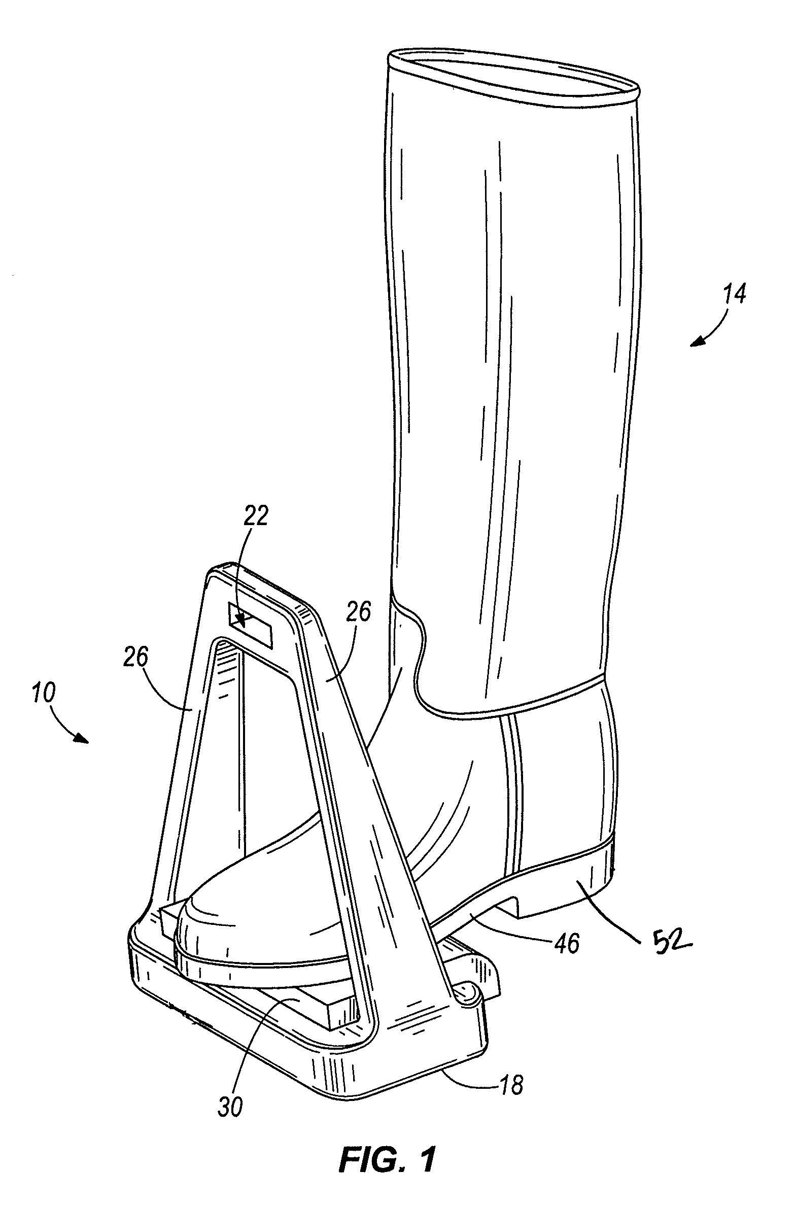
[0013]FIG. 1 illustrates a stirrup 10 and a riding boot 14 for use with one embodiment of the invention. The stirrup 10 and the riding boot 14 form a riding system for use with various riding animals. As shown in FIG. 1, the stirrup 10 includes a base 18, an eye 22 for a strap to connect the stirrup to a saddle, such as a leather strap, and two branches 26 extending between the base 18 and the eye 22. The stirrup 10 may be formed of various materials, such as steel, stainless steel, iron, plated nickel, plastic, aluminum, wood, leather, and composites. Furthermore, the stirrup 10 may be formed of any metal as is known in the art. The magnetic stirrup 10 may be either English-style, as shown, or Western-style.

[0014]In the illustrated embodiment, a tread or foot pad 30 is removably coupled to the base 18 using fasteners (e.g., screws) inserted through apertures in the base 18. In a further embodiment, the foot pad 30 may be permanently attached to the base 18. The foot pad 30 may incl...


PUM


Abstract

A riding boot attachment for use with a riding boot includes a body member having a first surface, a second surface, and at least two openings for receiving the riding boot. The body member receives at least a portion of the riding boot and is shaped and configured to conform to a contour of the riding boot. The riding boot attachment also includes a sole for engaging a stirrup, the sole coupled to the first surface of the body member, and a magnetic member coupled to the sole.

Description

CROSS-REFERENCE TO RELATED APPLICATIONS[0001]This application is a continuation-in-part and claims priority to co-pending U.S. patent application Ser. No. 12 / 403,638, entitled “STIRRUP”, filed on Mar. 13, 2009 by Paul H. Yanke and Charles H. Yanke, which claims priority to U.S. Provisional Patent Application No. 61 / 036,819, entitled “STIRRUP”, filed Mar. 14, 2008 by Scott H. Yanke, Patricia A. Van Housen and Paul H. Yanke, and to U.S. Provisional Patent Application No. 61 / 052,773, entitled “STIRRUP”, filed May 13, 2008 by Scott H. Yanke, Patricia A. Van Housen and Paul H. Yanke, the entire contents of which are hereby incorporated by reference.BACKGROUND[0002]The present invention relates to a boot attachment for a riding boot, and more particularly, to a magnetic riding boot attachment that magnetically attracts a stirrup.[0003]Typically, stirrups attach to a saddle by straps. In equestrian events and activities, a rider's feet are placed into the stirrups, thereby allowing the rid...

Claims


Application Information

Patent Timeline
IPC IPC(8): A43B5/00
CPCA43B1/0054A43B5/00A43B5/006A43B5/14A43B5/18B68C2003/0091A43B13/22B68C3/00B68C2003/0033B68C2003/0083A43B13/00
Inventor YANKE, PAUL H.YANKE, ASHLEY M.
Owner ONTYTE
Why Eureka
Try Eureka