Device for electrohydraulic forming of sheet metal

a technology of electrohydraulic forming and sheet metal, which is applied in the field of electrohydraulic forming devices of sheet metal, can solve the problems of limited number of spark gaps that can be switched in series, and achieve the effect of increasing the productivity of the devi

Inactive Publication Date: 2011-03-10
THEWES REINHOLD
View PDF28 Cites 5 Cited by
  • Summary
  • Abstract
  • Description
  • Claims
  • Application Information

AI Technical Summary

Benefits of technology

[0010]It is an object of the present invention to remedy this situation and to provide a device for electrohydraulic forming of sheet metal that allows efficient forming of sheet metal even with larger forming areas, for series production. According to the invention, this task is accomplished by disposing at least one potential-free bridge element between at least two electrodes within the electrode frame.

Problems solved by technology

This method has the disadvantage that the electrical discharge of an electrode pair brings about an essentially point-shaped energy discharge, and this discharge results in a hydraulic field of effect having a diameter of maximally 200 mm.
If, on the other hand, multiple electrode pairs are switched in series, then the problem of simultaneous ignition is eliminated, but the possible number of spark gaps that can be switched in series is limited by the required ignition voltage.

Method used


Image

  • Device for electrohydraulic forming of sheet metal
  • Device for electrohydraulic forming of sheet metal
  • Device for electrohydraulic forming of sheet metal

Examples


Embodiment Construction

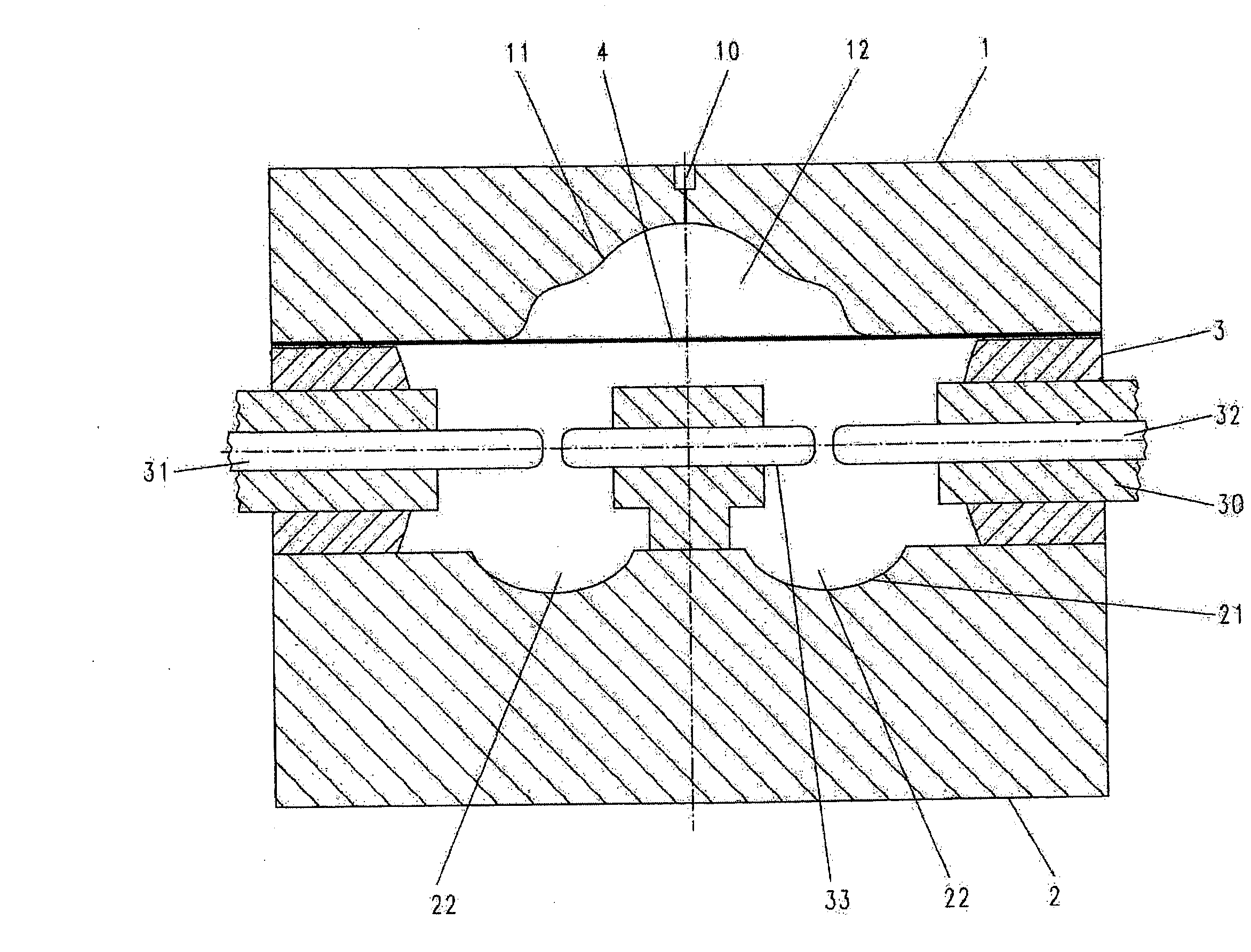
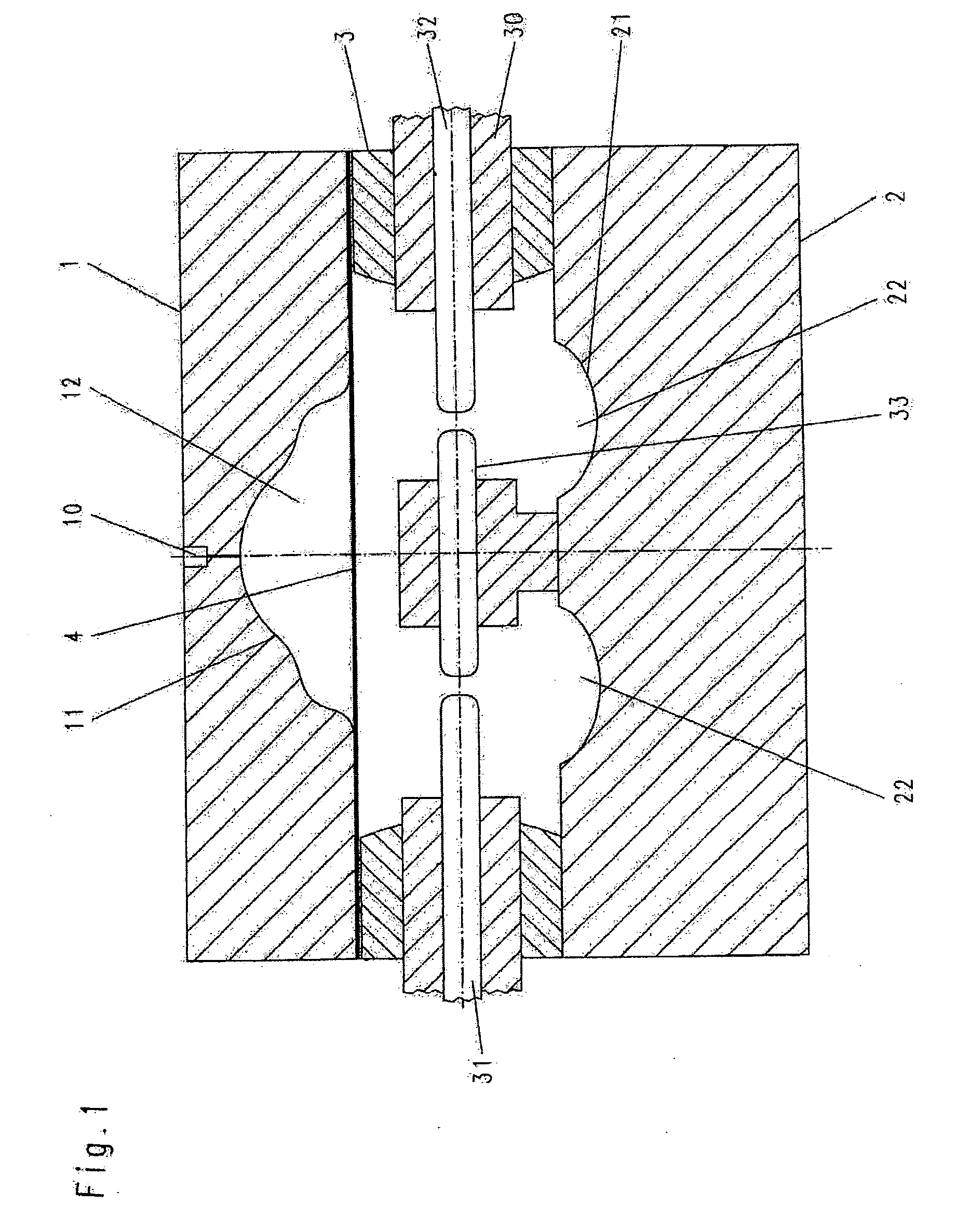
[0026]Turning now in detail to the drawings, FIG. 1 shows an exemplary embodiment of a device for electrohydraulic forming of sheet metal essentially made up of an upper die part 1 and a lower die part 2, between which an electrode frame 3 is disposed. A metal sheet 4 can be clamped in place between electrode frame 3 and upper die part 1, in fluid-tight manner.

[0027]A die plate 11 is placed into upper die part 1, which plate has the contour to be shaped into metal sheet 4. Furthermore, a line 10 for evacuating the chamber formed by metal sheet 4 laid in and die plate 11 is provided in upper die part 1.

[0028]Lower die part 2 has reflectors 21 configured essentially parabolically or elliptically, which are disposed to lie opposite die plate 11 of upper die part 1. Reflectors 21 serve to reflect discharge energy that impacts them, in the direction of die plate 11.

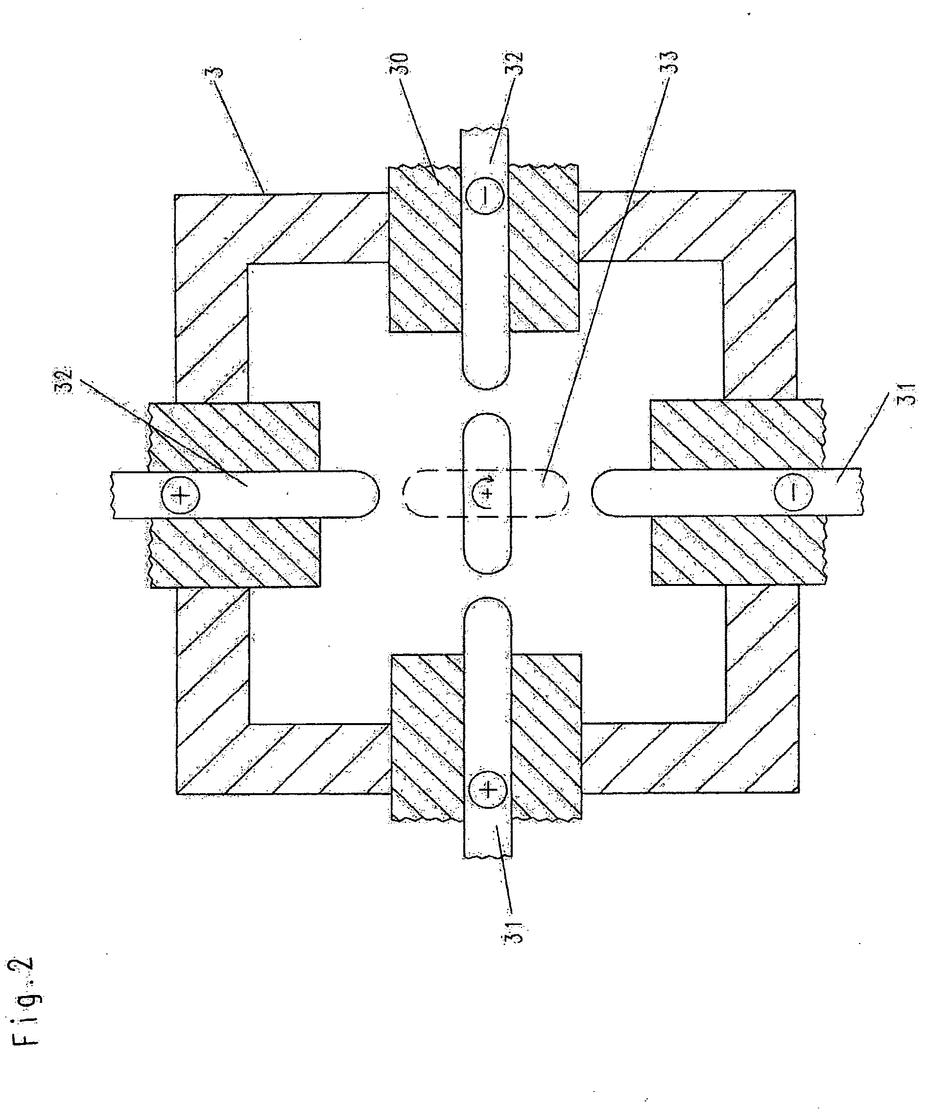
[0029]An electrode frame 3 is disposed on lower die part 2. In the exemplary embodiment according to FIG. 2, electrode frame...


PUM

PropertyMeasurementUnit
diameteraaaaaaaaaa
thicknessaaaaaaaaaa
diametersaaaaaaaaaa

Abstract

A device for electrohydraulic forming of sheet metal includes an upper die part having a die plate, and a lower die part on which an electrode frame is disposed. The frame accommodates at least two electrodes, and a metal sheet can be clamped in place between the die plate and the electrode frame in fluid-tight manner. At least one potential-free bridge element is disposed between at least two electrodes, within the electrode frame.

Description

CROSS REFERENCE TO RELATED APPLICATIONS[0001]Applicant claims priority under 35 U.S.C. §119 of European Application No. 09011365 filed on Sep. 4, 2009.BACKGROUND OF THE INVENTION[0002]1. Field of the Invention[0003]The invention relates to a device for electrohydraulic forming of sheet metal including an upper die part having a die plate and a lower die part on which an electrode frame is disposed, which frame accommodates at least two electrodes whereby a metal sheet can be clamped in place between die plate and electrode frame.[0004]2. The Prior Art[0005]Various methods, tailored to the product, in each instance, are used for forming metal sheets. In the case of conventional pressing, the metal sheet to be formed is pressed against the die plate that has the desired contour, by way of a punch. In the case of hydroforming pressing, however, the sheet metal is pressed against the die place using a fluid, preferably water, that has been put under pressure. In the hydroforming method,...

Claims


Application Information

Patent Timeline
Patent Type & Authority Applications(United States)
IPC IPC(8): B21D26/00
CPCB21D26/12
Inventor THEWES, REINHOLD
Owner THEWES REINHOLD
Why Eureka
Try Eureka