Method For Calibrating Stack Height Sensing In A Media Stack Height Monitoring System In An Image Forming Machine

a technology of stack height sensing and monitoring system, which is applied in the field of image forming machines, can solve the problems of impending depletion of stack, delay in job completion, and inability to meet the needs of image forming devices, so as to reduce the cost of the approach, eliminate additional contact, and save costs

Active Publication Date: 2011-03-10
LEXMARK INT INC
View PDF15 Cites 1 Cited by
  • Summary
  • Abstract
  • Description
  • Claims
  • Application Information

AI Technical Summary

Benefits of technology

[0008]Embodiments of the present invention meet this need by providing an innovation that does not use stack contact and movement of a separate arm with a flag. Instead, the innovation uses stack contact and movement of a pick arm, a standard component on an image forming machine, which changes its angular position as the stack height changes as part of its normal single function of feeding sheets from the top of the stack. Therefore, underlying this innovation is the recognition by the inventors herein that the pick arm heretofore has been underutilized and could also be employed to perform this additional sensing function concurrently with its normal sheet picking or feeding function. Now the pick arm serves dual functions: its normal sheet feeding function plus performing part of a stack height sensing function. Assuming in terms of cost that the sensors per se utilized in the above-cited patent and in this innovation are at least equivalent, the stack height monitoring system provided by embodiments of the present invention reduces the cost of the approach of the above-cited patent through eliminating the requirement for a separate arm by mounting the sensor directly on the pick arm. This brings this innovation into the realm of cost-effectiveness. In addition to the cost savings by doing away with the need for a separate arm, the innovation also eliminates the additional contact by the arm with the media stack which can increase drag on the top sheet of the stack and negatively impact the performance of the picking operation. The innovation also involves a method of calibrating stack height sensing that enhances the utility of this approach for the user.

Problems solved by technology

As a whole, image forming devices, such as inkjet printers, that feed sheets of media from a stack are deficient in their means to provide a warning of an impending depleted stack condition.
As a consequence, if a user sends a job to such a device without knowing if there are a sufficient number of sheets in the stack for its completion, and if the stack depletes during the print job, the user will have to reload the stack and restart, causing a delay in the job's completion.

Method used


Image

  • Method For Calibrating Stack Height Sensing In A Media Stack Height Monitoring System In An Image Forming Machine
  • Method For Calibrating Stack Height Sensing In A Media Stack Height Monitoring System In An Image Forming Machine
  • Method For Calibrating Stack Height Sensing In A Media Stack Height Monitoring System In An Image Forming Machine

Examples


Embodiment Construction

[0018]The present invention now will be described more fully hereinafter with reference to the accompanying drawings, in which some, but not all embodiments of the invention are shown. Indeed, the invention may be embodied in many different forms and should not be construed as limited to the embodiments set forth herein; rather, these embodiments are provided so that this disclosure will satisfy applicable legal requirements. Like numerals refer to like elements throughout the views.

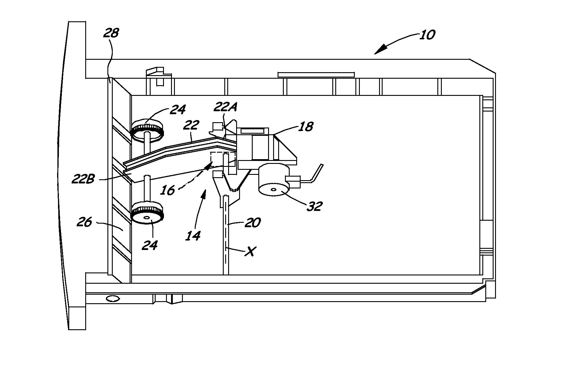
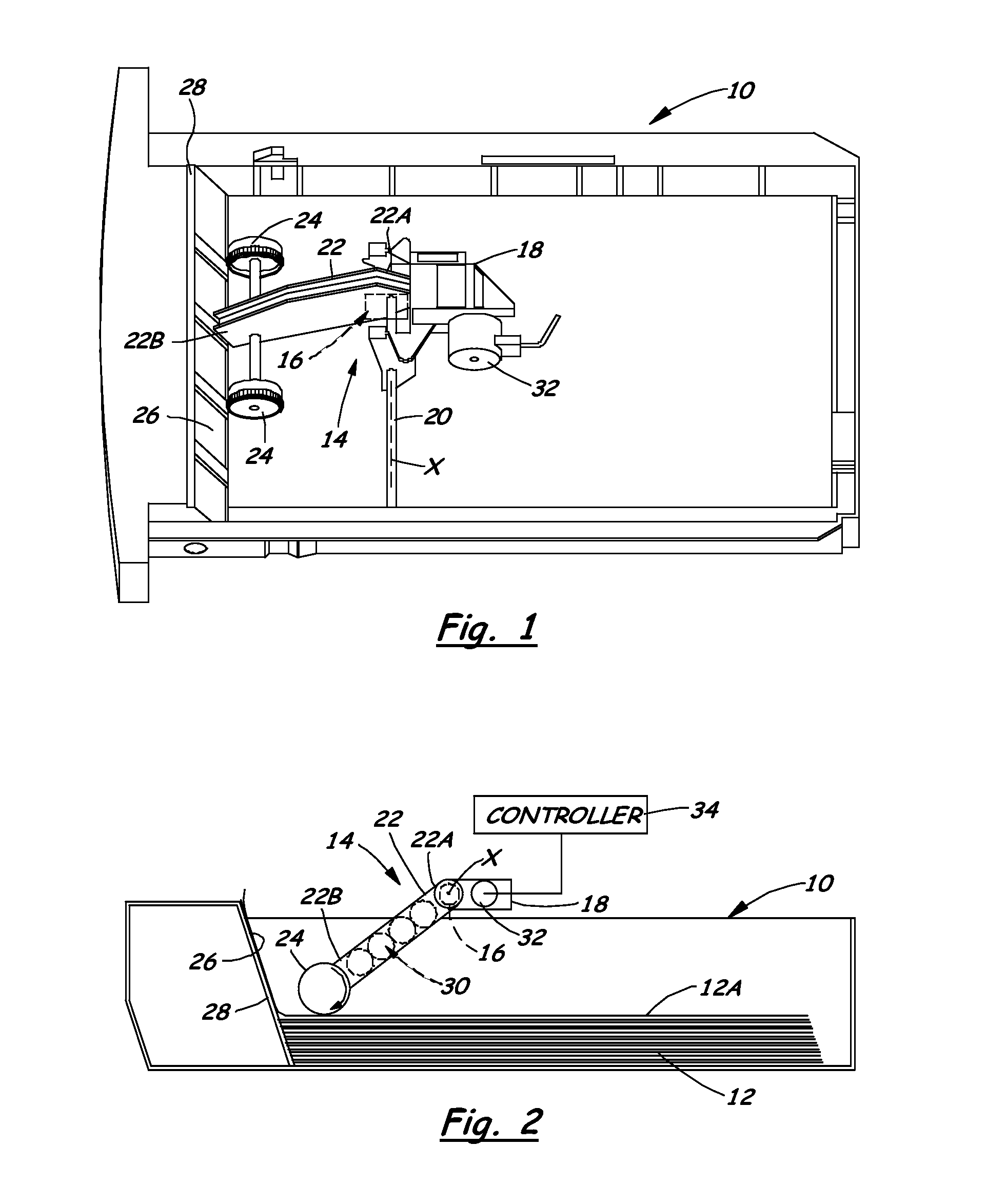
[0019]Referring now to FIGS. 1 and 2, there is illustrated a media input tray 10 supporting a media stack 12 and having a media sheet feeding pick mechanism 14 (also called an auto compensating pick mechanism). As shown in FIG. 2, a sensing mechanism 16, of a system and method for monitoring the height of the media stack 12 in accordance with embodiments of the present invention, may be applied to the pick mechanism 14 for sensing change in the media stack height. As seen in FIG. 1, the pick mechanism 14...


PUM


Abstract

A method of calibrating stack height sensing in a media stack height monitoring system in an image forming machine includes sensing the angular position of a pick mechanism arm, generating electrical signals having levels correlated to the pick mechanism arm angular positions that correspond to different stack height levels, measuring and storing at least one value corresponding to the level of the electrical signal at least at one of two calibration points: “full load” and “stack out” conditions of the media stack, estimating either the amount or percent of media sheets remaining in the media stack corresponding to measured and stored value of the electrical signal level at the at least one calibration point, and indicating either of the amount or percent of media sheets remaining in the media stack.

Description

CROSS REFERENCES TO RELATED APPLICATIONS[0001]This application is a divisional of parent application Ser. No. 12 / 488,345, filed Jun. 19, 2009, entitled “System and Method or Monitoring Image Forming Machine Media Stack Height and Method of Calibrating Stack Height Sensing in the Monitoring System,” which is hereby incorporated by reference. This patent application is related to the subject matter of co-pending U.S. patent application Ser. Nos. 12 / 266,232 filed Nov. 6, 2008 and 12 / 326,230 filed Dec. 2, 2008, assigned to the assignee of the present invention. The entire disclosures of these patent applications are hereby incorporated herein by reference.BACKGROUND[0002]1. Field of the Invention[0003]The present invention relates generally to an image forming machine and, more particularly, to a system and method for monitoring media stack height in an image forming machine and a method of calibrating stack height sensing in the media stack height monitoring system.[0004]2. Description...

Claims


Application Information

Patent Timeline
Patent Type & Authority Applications(United States)
IPC IPC(8): G01P21/00
CPCB65H3/0684B65H2511/152B65H2511/212B65H2553/51B65H2801/06B65H2220/03B65H2220/02B65H2220/11B65H2511/15
Inventor GAGNON, DANIEL ROBERTRUMFORD, ROBERT WARRENWRITT, JOHN THOMAS
Owner LEXMARK INT INC
Why Eureka
Try Eureka